


Portenta Vision Shield - Ethernet
Professional computer vision, directional audio detection, Ethernet, and JTAG for Arduino Portenta.
The Portenta Vision Shield is also available with LoRa® connectivity. Check it out here!
Overview
The Portenta Vision Shield brings industry-rated features to your Portenta. This hardware add-on will let you run embedded computer vision applications, connect wirelessly or via Ethernet to the Arduino Cloud or your own infrastructure, and activate your system upon the detection of sound events.
The shield comes with:
- a 320x320 pixels camera sensor: use one of the cores in Portenta to run image recognition algorithms using the OpenMV for Arduino editor
- a 100 Mbps Ethernet connector: get your Portenta H7 connected to the wired Internet
- two on-board microphones for directional sound detection: capture and analyze sound in real time
- JTAG connector: perform low-level debugging of your Portenta board or special firmware updates using an external programmer
- SD-Card connector: store your captured data in the card, or read configuration files
The Vision Shield Ethernet has been designed to work with the Portenta H7. The Portenta boards feature multicore 32-bit ARM® Cortex® processors running at hundreds of megahertz, with megabytes of program memory and RAM. Portenta boards come with WiFi and Bluetooth®. Purchase this Shield together with the Portenta H7 for full performance.
Embedded Computer Vision Made Easy
Arduino has teamed up with OpenMV to offer you a free license to the OpenMV IDE, an e
asy way into computer vision using MicroPython as a programming paradigm. Download the OpenMV for Arduino Editor from our professional tutorials site and browse through the examples we have prepared for you inside the OpenMV IDE. Companies across the whole world are already building their commercial products based on this simple-yet-powerful approach to detect, filter, and classify images, QR codes, and others.

QR code detection example
Blob analysis example
Debugging With Professional Tools
Connect your Portenta H7 to a professional debugger through the JTAG connector. Use professional software tools like the ones from Lauterbach or Segger on top of your board to debug your code step by step. The Vision Shield exposes the required pins for you to plug in your external JTAG.
Getting Started
The Portenta tutorials section at the Arduino Docs website contains all the information you need to configure the Portenta H7, as well as the Vision Shield, and the OpenMV editor for computer vision applications.
Need Help?
Check the Arduino Forum for questions about the Arduino Language, or how to make your own Projects with Arduino. Need any help with your board please get in touch with the official Arduino User Support as explained in our Contact Us page.
Warranty
You can find here your board warranty information.
Tech specs
The Arduino Vision Shield is an active add-on to the Portenta family of boards.
| Camera | Himax HM-01B0 camera module (manufacturer site) |
| Resolution | 320 x 320 active pixel resolution with support for QVGA |
| Image sensor | High sensitivity 3.6μ BrightSense™ pixel technology |
| Microphone | 2 x MP34DT05 (datasheet) |
| Length | 66 mm |
| Width | 25 mm |
| Weight | 11 gr |
Conformities
Resources for Safety and Products
Manufacturer Information
The production information includes the address and related details of the product manufacturer.
Arduino S.r.l.
Via Andrea Appiani, 25
Monza, MB, IT, 20900
https://www.arduino.cc/
Responsible Person in the EU
An EU-based economic operator who ensures the product's compliance with the required regulations.
Arduino S.r.l.
Via Andrea Appiani, 25
Monza, MB, IT, 20900
Phone: +39 0113157477
Email: support@arduino.cc
Documentation
Learn more about the Portenta Vision Shield using the following files:
SCHEMATICS IN .PDF DATASHEET IN .PDF
Pinout Diagram
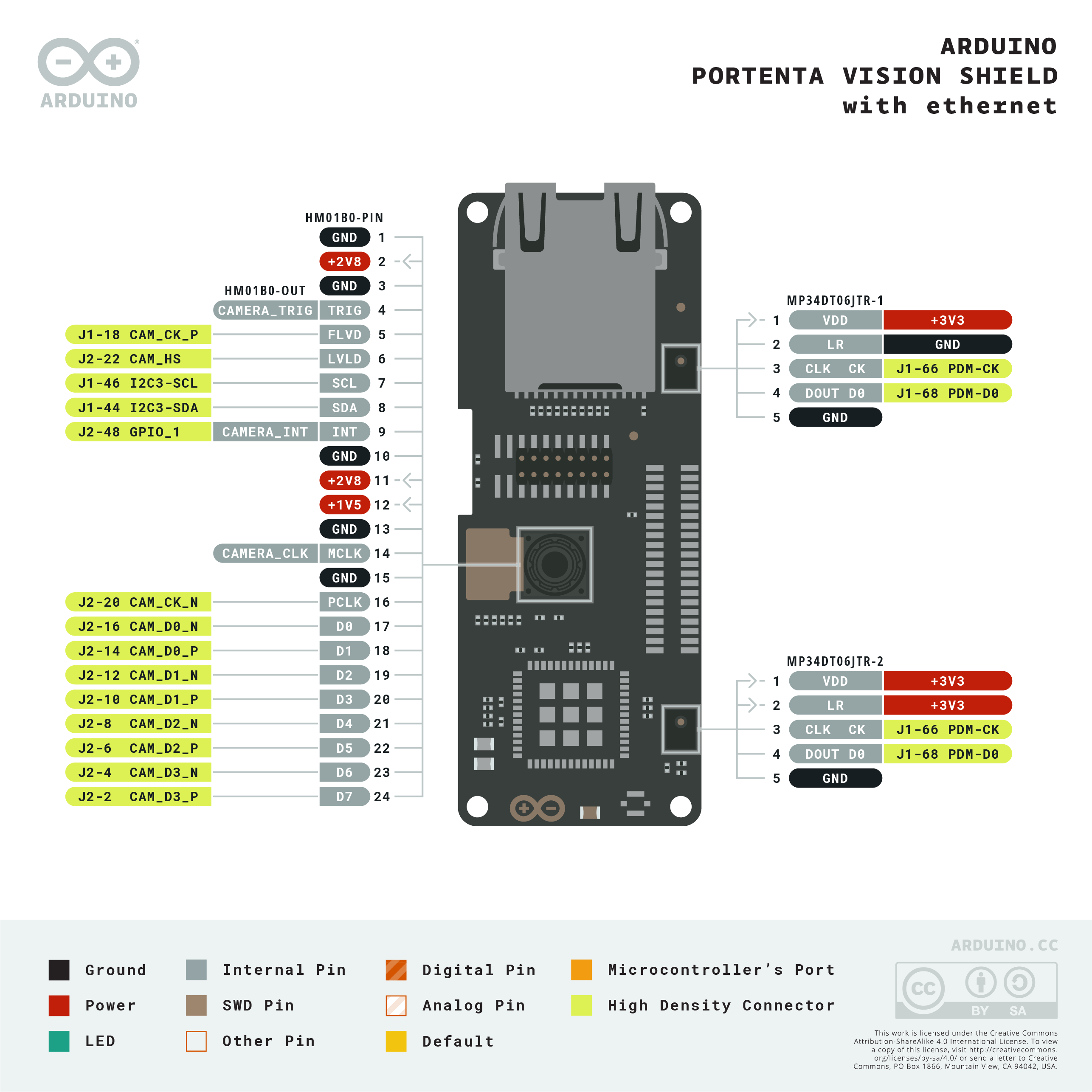
Download the full pinout diagram as PDF here.
Learn more
Get Inspired
This project detects water leak and records the temperature and humidity reading at the time of leak and sends it to the Adafruit cloud.
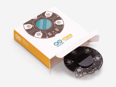
By popular demand, we are pleased to announce that it’s now possible to buy the Arduino MKR IoT Carrier. Originally forming a key part of the Arduino Oplá IoT Kit, we’ve responded to our community to make the carrier available on its own, thus enabling you to benefit from having a bunch of sensors, actuators, and a display all featured on the one board — making it quicker and easier to take your IoT projects to the next level. Featuring a large set of built-in sensors and actuators as well as a useful color display, the carrier lets you focus on prototyping your IoT ideas right away by saving on the hassle of wiring and soldering these components. The carrier can become a WiFi, LoRa, NB-IoT or GSM-compatible device by seamlessly connecting to any MKR family board. Building a user interface for these boards is easy with the embedded color OLED screen, five capacitive touch buttons, and the five RGB LEDs. The integrated sensors (temperature, humidity, pressure, RGBC light, gesture and proximity) allow you to map the environment around the carrier, and should you need to capture any other data there are over 100 additional Grove sensors that can easily be connected directly to the carrier. Here’s are quick demo of the carrier's capabilities! (Special shout out to Mirko Pacioni and Filo Connesso for creating this demo.) Capture and store all the data locally on an SD card, or connect your MKR family board to the IoT Cloud for real-time data captured, storage, and visualization. The MKR IoT Carrier features: Round OLED displayFive RGB LEDsFive capacitive touch buttonsOn-board sensors (temperature, humidity, pressure, RGBC light, gesture and proximity)BuzzerIMU (Three-axis accelerometer sensor and three-axis gyroscope sensor)Two 24V relaysMicroSD card holder (SD card not included)Plug-and-play Grove connectors for external sensors — two analog and one digital (I2C)18650 Li-ion rechargeable battery holder (battery not


