Overview
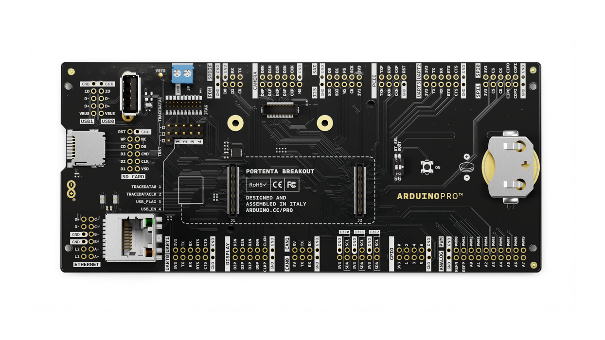
Portenta Breakout board is designed to help hardware engineers and makers to prototype and help test devices connections and capacity within the Portenta family boards (e.g. the Portenta H7).
It makes all high-density connectors’ signals individually accessible, making it quick and easy to connect and test external hardware components and devices as normally needed during development in the lab.
Target areas
Prototyping
Application examples
This product is designed to work alongside the Portenta family. Please check the Getting Started guide of your Portenta board.
Product Development: The Portenta Breakout board reduces development time for industrial grade solution automation based on the Portenta line.
Technical Education: The Portenta Breakout board can act as the first point of entry for technician education in industrial grade control and embedded systems.
Features
- Power ON Button
- Boot mode DIP switch
- Connectors
- USBA
- RJ45 up to 1Gb/s
- Micro SD card
- MIPI 20T JTAG with trace capability - Power
- CR2032 RTC Lithium Battery backup
- External power terminal block - I/O
- Break out all Portenta High Density connector signals
- Male/female HD connectors allow interposing breakout between Portenta and shield to debug signals - Compatibility
- Standard Portenta High Density connector pinout - Safety information
- Class A
Tech specs
| USB port | USBA |
| Ethernet | RJ45 up to 1Gb/s (Supported on Portenta X8 only) |
| Memory slot | Micro SD card |
| Debug | MIPI 20T JTAG with trace capability |
| Connectors | HD male/female |
| RTC power battery | CR2032 |
| Length | 164 mm |
| Width | 72 mm |
| Weight | 0,069 Kg |
Conformities
Resources for Safety and Products
Manufacturer Information
The production information includes the address and related details of the product manufacturer.
Arduino S.r.l.
Via Andrea Appiani, 25
Monza, MB, IT, 20900
https://www.arduino.cc/
Responsible Person in the EU
An EU-based economic operator who ensures the product's compliance with the required regulations.
Arduino S.r.l.
Via Andrea Appiani, 25
Monza, MB, IT, 20900
Phone: +39 0113157477
Email: support@arduino.cc
Documentation
Study how the Portenta Breakout Carrier works using following files:
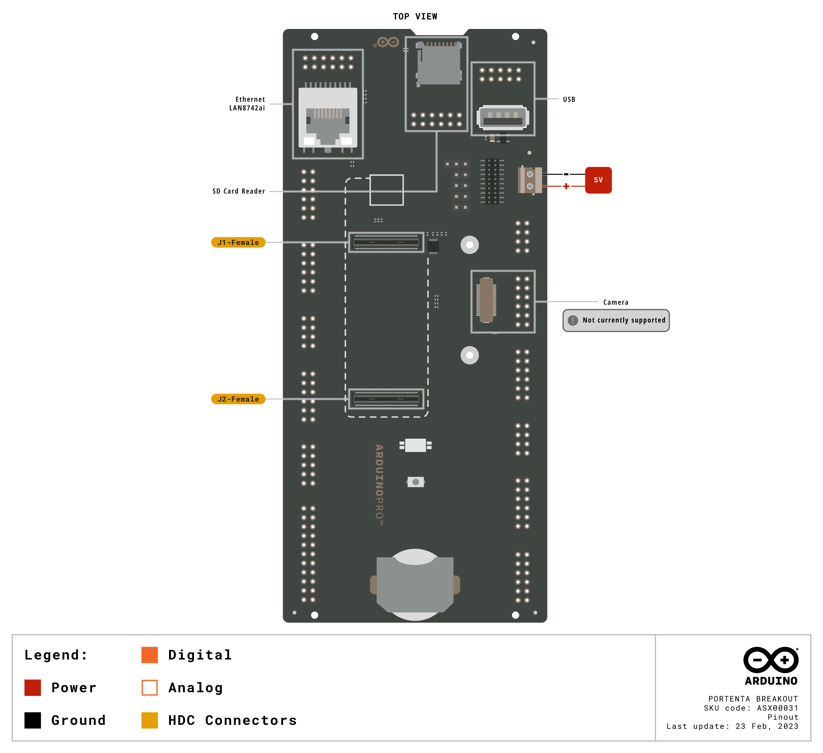
Pinout Diagram
Learn more about the portenta's pinout by reading the pinout documentation.

Download the full pinout diagram as PDF here.
Interactive Board Viewer
Learn more
Get Inspired

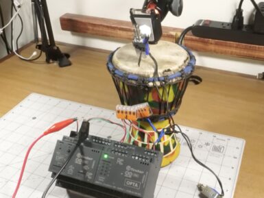
Makers have long asked the question “why bother with an expensive PLC when I can just use an Arduino?” The answer comes down to the priorities and needs of industrial clients. In a factory automation setting, the client will prioritize durability, reliability, and serviceability over the one-time purchase price of the device itself. But to prove that Arduino’s professional turnkey solutions are just as easy to use as their developer-focused educational counterparts, Jeremy Cook leveraged an Arduino Opta micro PLC to build a drum machine. This isn’t any old drum machine that plays sound samples or synthesized notes, but rather a robotic drum machine that makes noise by banging on stuff like a true percussion instrument. Cook could have built this with any Arduino board and a few relays, but instead chose to implement the Opta and new Opta Digital Expansion. That is robust enough for serious commercial and industrial applications, but is still simple to program with the familiar Arduino IDE. Programmers can also use conventional PLC languages if they prefer. In this case, Cook made noise with relays and solenoids. The Opta has four built-in relays and Cook’s sketch flips one of them to make a sound analogous to a hi-hat. Cook added an Arduino Pro Opta Ext D1608S module with its solid-state relays for the other two “drums.” One of those fires a solenoid that taps a small hand drum (the kick drum sound), while the other controls a solenoid that hits a power supply enclosure (the snare sound). Together, those three sounds can cover the basics of a drum track. Cook’s sketch is a drum sequencer program that stores each sound sequence as array, looping through them until turned off. An Opta may be overkill for a project like this one, but this does a great job of demonstrating the ease at which an Arduino user can transition to professional PLC work.


