


Overview
DC/DC step-up converter with particularly small dimensions (51 x 21.5 x 13 mm), capable of converting a DC voltage between 3.5 and 30 volts into an output voltage from 4 to 30 volts (adjustable via trimmer).
Tech specs
- Input voltage: from 3.5 V to 30 V
- Output current: 2 A (max. 3 A - using a fan to dissipate heat)
- Adjustable output voltage: from 4 V to 30 V
- Dimensions (mm): 51 x 21.5 x 13
Conformities
Get Inspired
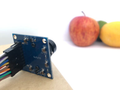
If you’re interested in embedded machine learning (TinyML) on the Arduino Nano 33 BLE Sense, you’ll have found a ton of on-board sensors — digital microphone, accelerometer, gyro, magnetometer, light, proximity, temperature, humidity and color — but realized that for vision you need to attach an external camera. In this article, we will show you how to get image data from a low-cost VGA camera module. We’ll be using the Arduino_OVD767x library to make the software side of things simpler. Hardware setup To get started, you will need: Arduino Nano 33 BLE Sense with headersOV7670 CMOS VGA Camera Module 16x female to female jumper wiresA microUSB cable to connect to your Arduino You can of course get a board without headers and solder instead, if that's your preference. The one downside to this setup is that (in module form) there are a lot of jumpers to connect. It’s not hard but you need to take care to connect the right cables at either end. You can use tape to secure the wires once things are done, lest one comes loose. You need to connect the wires as follows: Software setup First, install the Arduino IDE or register for Arduino Create tools. Once you install and open your environment, the camera library is available in the library manager. Install the Arduino IDE or register for Arduino CreateTools > Manage Libraries and search for the OV767 libraryPress the Install button Now, we will use the example sketch to test the cables are connected correctly: Examples > Arduino_OV767X > CameraCaptureRawBytesUncomment (remove the //) from line 48 to display a test pattern Compile and upload to your board Your Arduino is now outputting raw image binary over serial. To view this as an image we’ve included a special application to view the image output from the camera using Processing. Processing is a simple programming environment that was created by graduate students at MIT Media Lab to make


