


Arduino IoT Bundle
The Arduino IoT Bundle is the best way to start exploring the world of connected devices using the Arduino Nano RP2040 Connect. Follow the 5 step by step tutorials to quickly learn how to build IoT devices.
Overview
Follow the 5 step by step tutorials we have prepared for you and combining the electronic components included in the bundle, you’ll quickly learn how to build devices that connect to the Arduino IoT Cloud.
The 5 step by step tutorials are:
Arduino IoT Cloud Compatible

Tech specs
Each bundle includes:
- 1 Arduino Nano RP2040 Connect
- 1 micro USB cable
- 1 400-point breadboard
- 70 solid-core jumper wires
- 2 stranded jumper wire
- 6 phototransistors
- 3 potentiometers (10k ohm)
- 10 pushbuttons
- 1 temperature sensor (TMP36)
- 1 tilt sensor
- 1 alphanumeric LCD (16 x 2 characters)
- 1 bright white
- 28 LEDs (1 RGB, 8 red, 8 green, 8 yellow, 3 blue)
- 1 small DC motor (6/9V)
- 1 small servo motor
- 1 piezo capsule (PKM17EPP-4001-B0)
- 1 H-bridge motor driver (L293D)
- 1 optocouplers (4N35)
- 2 MOSFET transistors (IRF520)
- 5 capacitors (100uF)
- 5 diodes (1N4007)
- 1 male pin strip (40 x 1)
- 20 resistors (220 ohm)
- 5 resistors (560 ohm)
- 5 resistors (1k ohm)
- 5 resistors (4.7k ohm)
- 20 resistors (10k ohm)
- 5 resistors (1M ohm)
- 5 resistors (10M ohm)
Resources for Safety and Products
Manufacturer Information
The production information includes the address and related details of the product manufacturer.
Arduino S.r.l.
Via Andrea Appiani, 25
Monza, MB, IT, 20900
https://www.arduino.cc/
Responsible Person in the EU
An EU-based economic operator who ensures the product's compliance with the required regulations.
Arduino S.r.l.
Via Andrea Appiani, 25
Monza, MB, IT, 20900
Phone: +39 0113157477
Email: support@arduino.cc
Get Inspired
Just a simple and enjoyable autonomous greenhouse
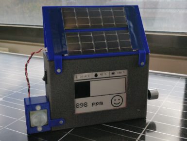
Humans are animals and like all animals, we evolved in mostly outdoor conditions where the air is nice and fresh. But modern society keeps most of us indoors the vast majority of the time, which could have negative health effects. There are many potential hazards, including a lack of sunlight and psychological effects, but CO2 may pose a more tangible risk. To keep tabs on that risk within classrooms, a team from Polytech Sorbonne built this small CO2 monitor. This CO2 monitor performs two functions: it shows anyone nearby the CO2 levels in the area and it uploads that data over LoRaWAN to a central hub that can track the levels across many locations. A school could, for example, put one of these CO2 monitors in every classroom. An administrator could then see the CO2 levels in every room in real time, along with historical records. That would alert them to immediate dangers and to long term trends. At the heart of this CO2 monitor is an Arduino MKR WAN 1310 development board, which has built-in LoRa® connectivity. It uses a Seeed Studio Grove CO2, temperature, and humidity sensor to monitor local conditions. To keep power consumption to a minimum, the data displays on an e-ink screen and an Adafruit TPL5110 timer only wakes the device up every ten minutes for an update. Power comes from a lithium-ion battery pack, with a DFRobot solar charger topping up the juice. It uploads data through The Things Network to a PlatformIO web interface. An Edge Impulse machine learning model detects anomalies, so it can sound a warning even if nobody is watching. The enclosure is 3D-printable.
FAQs
I plugged the board to my PC / MAC but I cannot see the serial port listed in the IDE, so I can't upload my sketch to the board!
- Make sure the foam that protects the boards’ pins is removed.
- Try connecting the board with another USB cable.
- Try connecting the board to another USB port. If possible, avoid USB-hubs.
You can see more information and other things to try in this Help Center article.
Do I need to subscribe to the Arduino IoT Cloud to build the projects described in the tutorials?
No, all the projects can be built using the free plan of the Arduino IoT Cloud. Click here to see what is included in the plan.
How to enable the 5V / VUSB pin?
The 5V pin is disabled by default. You can locate on the bottom of the board on the VBUS pin two pads, shorting these will enable 5V output. More info on this here.
Where can I find the step by step tutorials?
You can find the step by step tutorials at arduino.cc/iot-bundle


