Overview
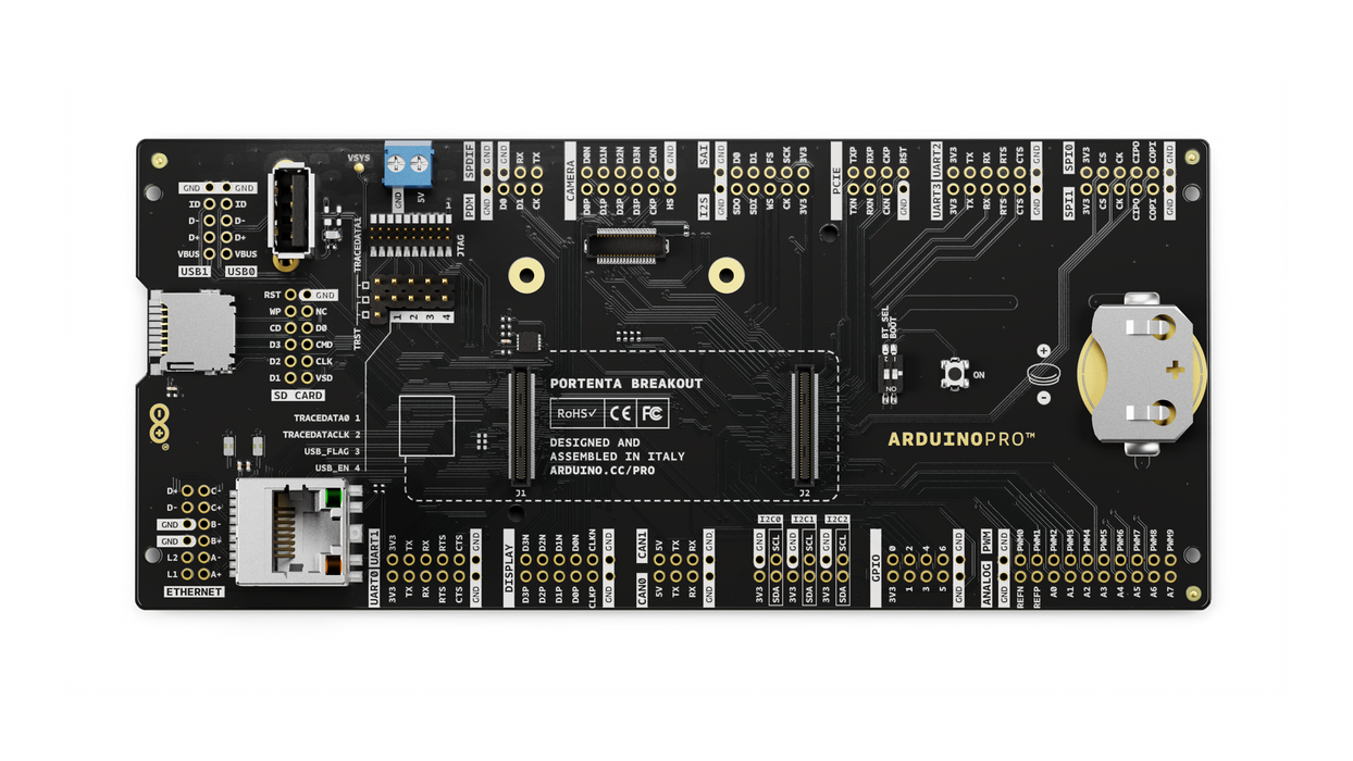
Portenta Breakout board is designed to help hardware engineers and makers to prototype and help test devices connections and capacity within the Portenta family boards (e.g. the Portenta H7).
It makes all high-density connectors’ signals individually accessible, making it quick and easy to connect and test external hardware components and devices as normally needed during development in the lab.
Target areas
Prototyping
Application examples
This product is designed to work alongside the Portenta family. Please check the Getting Started guide of your Portenta board.
Product Development: The Portenta Breakout board reduces development time for industrial grade solution automation based on the Portenta line.
Technical Education: The Portenta Breakout board can act as the first point of entry for technician education in industrial grade control and embedded systems.
Features
- Power ON Button
- Boot mode DIP switch
- Connectors
- USBA
- RJ45 up to 1Gb/s
- Micro SD card
- MIPI 20T JTAG with trace capability - Power
- CR2032 RTC Lithium Battery backup
- External power terminal block - I/O
- Break out all Portenta High Density connector signals
- Male/female HD connectors allow interposing breakout between Portenta and shield to debug signals - Compatibility
- Standard Portenta High Density connector pinout - Safety information
- Class A
Tech specs
| USB port | USBA |
| Ethernet | RJ45 up to 1Gb/s (Supported on Portenta X8 only) |
| Memory slot | Micro SD card |
| Debug | MIPI 20T JTAG with trace capability |
| Connectors | HD male/female |
| RTC power battery | CR2032 |
| Length | 164 mm |
| Width | 72 mm |
| Weight | 0,069 Kg |
Conformities
Resources for Safety and Products
Manufacturer Information
The production information includes the address and related details of the product manufacturer.
Arduino S.r.l.
Via Andrea Appiani, 25
Monza, MB, IT, 20900
https://www.arduino.cc/
Responsible Person in the EU
An EU-based economic operator who ensures the product's compliance with the required regulations.
Arduino S.r.l.
Via Andrea Appiani, 25
Monza, MB, IT, 20900
Phone: +39 0113157477
Email: support@arduino.cc
Documentation
Study how the Portenta Breakout Carrier works using following files:
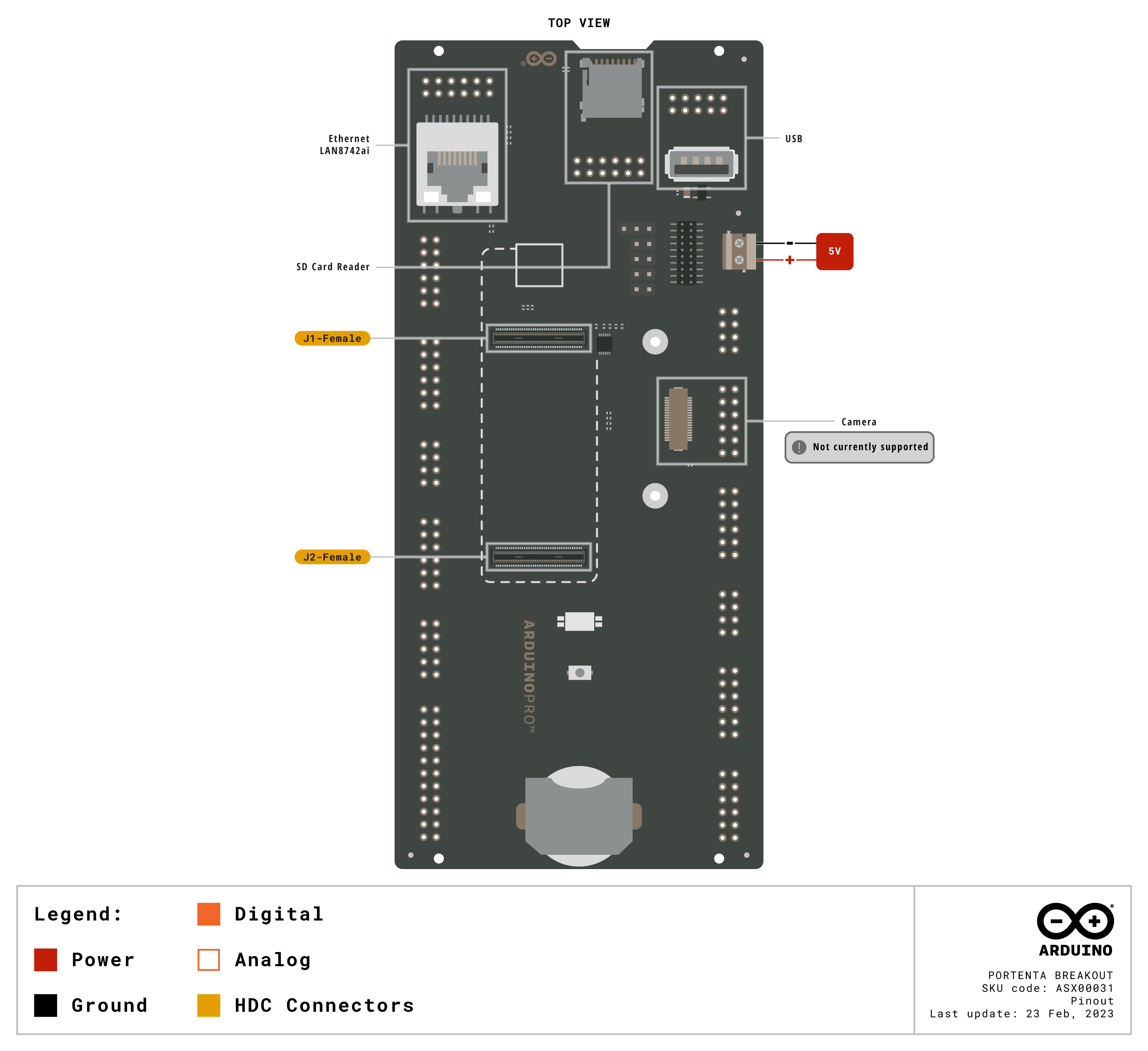
Pinout Diagram
Learn more about the portenta's pinout by reading the pinout documentation.

Download the full pinout diagram as PDF here.
Interactive Board Viewer
Learn more
Get Inspired
Using the Garmin LIDARLite v3HP, Arduino MKR WIFI 1010 and Pushsafer to detect an intruder and send a push notification to a smartphone.

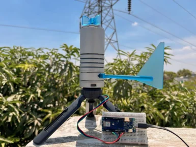
Being able to monitor the weather in real-time is great for education, research, or simply to analyze how the local climate changes over time. This project by Hackster.io user Pradeep explores how he was able to design a simple station outdoors that could communicate with a cloud-based platform for aggregating the sensed data. The board Pradeep selected is the Arduino MKR WiFi 1010 owing to its low-power SAM D21 microcontroller and Wi-Fi/BLE connectivity for easy, wireless communication. After configured, he connected a DFRobot Lark Weather Station, which contains sensors for measuring wind speed/direction, temperature, humidity, and barometric pressure — all in a compact device. Every second, the MKR WiFi 1010’s sketch polls the sensors for new data over I2C before printing it to USB. The cloud integration aspect was achieved by leveraging Qubitro’s platform to collect and store the data for later visualization and analysis. To set it up, Pradeep created a new device connection and copied the resulting MQTT endpoint/token into his sketch. Then once new data became ready, it got serialized into a JSON payload and sent to the topic where a variety of widgets could then show dials and charts of each weather-related metric. To read more about this DIY weather station, you can visit Pradeep’s project write-up here.


