


Proto Shield Rev3 (Uno Size)
Overview
The ProtoShield makes it easy for you to design custom circuits. You can easily solder TH or SMD ICs on the prototyping area to test them with your Arduino board. The SMD area is designed for a maximum of 24 pins SOIC integrated circuit and the TH area contains a lot of space for the needed components around your project. You can even stick a mini breadboard (not included) on the protoarea for solderless operation. The proto area includes also two power lines (IOREF and GND), two LEDs pads and SPI signals breakout pads for boards with SPI only on the ICSP header like Zero.
Key features:
- 1.0 Arduino Pinout
- 1 ICSP Connector footprint
- 2 LEDs and resistor footprint
- IOREF and GND power lines
- SPI signals pads
- 24 pin SMD footprint (50 mils pitch)
You can find your board warranty information here.
Need Help?
- On Projects on the Arduino Forum
- On the Product itself throughour Customer Support
Conformities
Resources for Safety and Products
Manufacturer Information
The production information includes the address and related details of the product manufacturer.
Arduino S.r.l.
Via Andrea Appiani, 25
Monza, MB, IT, 20900
https://www.arduino.cc/
Responsible Person in the EU
An EU-based economic operator who ensures the product's compliance with the required regulations.
Arduino S.r.l.
Via Andrea Appiani, 25
Monza, MB, IT, 20900
Phone: +39 0113157477
Email: support@arduino.cc
Documentation
OSH: Schematics
Arduino Proto Shield is open-source hardware! You can build your own board using the following files:
EAGLE FILES IN .ZIP SCHEMATICS IN .PDF
Power
The Proto Shield bring the power from the Arduino standard IOREF and GND pins to the two power bus rows placed between the Through Hole prototyping are, which can be used for powering correctly your project independently on the chosen board (3V3 or 5V).
SPI Connection
On the ICSP connector only 5V and GND are wired to the respective pins on the header. MOSI and MISO are present only on the connector and on the near extra pads.
For more information about the SPI communication see the SPI library.
Physical Characteristics
The maximum length and width of the Proto Shield PCB are 2.7 and 2.1 inches respectively. Three screw holes allow the shield to be attached to a surface or case. Note that the distance between digital pins 7 and 8 is 160 mil (0.16"), not an even multiple of the 100 mil spacing of the other pins.
Get Inspired

Another Slot Car Lap Counter, but if I did it anyone can do!
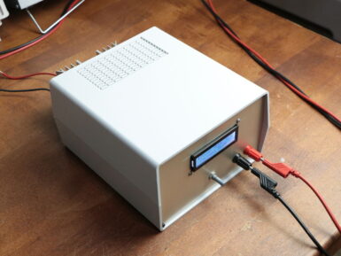
If you need a device which draws a certain amount of current and power for testing, then GreatScott! has just the solution. His project uses an Arduino Nano, along with a separate IC and a voltage divider, to measure both current and voltage input from the power source. It then employs this data to properly adjust a MOSFET, dissipating the correct amount of voltage and power as required. Interface is handled via a rotary encoder and a 16x2 I2C LCD display, and the electronics are housed in a solid-looking enclosure. As seen in the video below, the adjustable constant load features an impressively large heat sink, needed to take care of the 30V and 20A that the setup is capable of drawing.


