

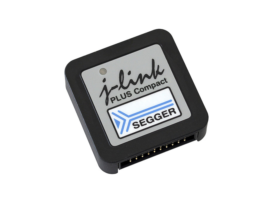
J-Link PLUS Compact
Sold outUSB powered JTAG debug probe supporting a large number of CPU cores.
Based on a 32-bit RISC CPU, it can communicate at high speed with the supported target CPUs.
SEGGER J-Link PLUS Compact is used around the world in tens of thousand places for development and production (flash programming) purposes.
Overview
Get the SEGGER J-Link PLUS Compact debug probe: a compact version of the J-Link PLUS. Mounts securely & unobtrusively into development and end user equipment.
Based on 32-bit RISC CPU, it communicates at high speed with supported target CPUs.
Thanks to a small size with two mounting holes, it can be placed into existing equipment housings.
Space can also be reserved for direct-to-PCB mounting.
All major IDEs (Eclipse & GDB-based IDEs) support J-Link debug probes, as does SEGGER Embedded Studio. 500,000 J-Links have been shipped so far, making this probably the most popular debug probe on the market for Arm cores and the de-facto standard.
Further Advantages
The SEGGER J-Link PLUS Compact has a built-in VCOM functionality and integrated licenses for unlimited breakpoints in flash memory, RDI/RDDI and J-Flash. It supports direct download into RAM and flash memory. It has a broad range of supported microcontrollers and CPUs.
Box Contents
- SEGGER J-Link PLUS Compact debug probe
- Micro USB cable
- 1" 20-pin ribbon cable (18 cm)
- Includes free software updates and one year of email support.
SEGGER J-Link debuggers are the most popular choice for optimizing the debugging and flash programming experience.
Documentation
Debugging with the Arduino IDE 2.0
Learn how to set up a Zero board, J-Link and Atmel-ICE debuggers with the Arduino IDE 2.0, and how to debug a program.
Using the Segger J-Link debugger with the MKR boards
Learn how to set up a MKR board with the Segger J-link debugger.
Get Inspired
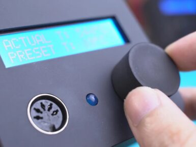
If you want to upgrade your soldering setup without spending a lot of money, then be sure to check out Angelo Casimiro's DIY Hakko 907 station. This low-cost device features an Arduino Nano to read the iron temperature via an LM358 op-amp, and regulates power to the handle and tip under PWM control using an IRFZ44N MOSFET. A potentiometer is implemented as a variable temperature knob, with the actual and preset temperature displayed on a 16x2 LCD screen, while an LED indicates whether the heating element is active. Everything is encased in a nicely printed and painted enclosure, which forms a brilliant little station that one could be proud to use. Full build instructions can be found here, including the PCB, code, and print files.


