


Proto Shield Rev3 (Uno Size)
Overview
The ProtoShield makes it easy for you to design custom circuits. You can easily solder TH or SMD ICs on the prototyping area to test them with your Arduino board. The SMD area is designed for a maximum of 24 pins SOIC integrated circuit and the TH area contains a lot of space for the needed components around your project. You can even stick a mini breadboard (not included) on the protoarea for solderless operation. The proto area includes also two power lines (IOREF and GND), two LEDs pads and SPI signals breakout pads for boards with SPI only on the ICSP header like Zero.
Key features:
- 1.0 Arduino Pinout
- 1 ICSP Connector footprint
- 2 LEDs and resistor footprint
- IOREF and GND power lines
- SPI signals pads
- 24 pin SMD footprint (50 mils pitch)
You can find your board warranty information here.
Need Help?
- On Projects on the Arduino Forum
- On the Product itself throughour Customer Support
Conformities
Resources for Safety and Products
Manufacturer Information
The production information includes the address and related details of the product manufacturer.
Arduino S.r.l.
Via Andrea Appiani, 25
Monza, MB, IT, 20900
https://www.arduino.cc/
Responsible Person in the EU
An EU-based economic operator who ensures the product's compliance with the required regulations.
Arduino S.r.l.
Via Andrea Appiani, 25
Monza, MB, IT, 20900
Phone: +39 0113157477
Email: support@arduino.cc
Documentation
OSH: Schematics
Arduino Proto Shield is open-source hardware! You can build your own board using the following files:
EAGLE FILES IN .ZIP SCHEMATICS IN .PDF
Power
The Proto Shield bring the power from the Arduino standard IOREF and GND pins to the two power bus rows placed between the Through Hole prototyping are, which can be used for powering correctly your project independently on the chosen board (3V3 or 5V).
SPI Connection
On the ICSP connector only 5V and GND are wired to the respective pins on the header. MOSI and MISO are present only on the connector and on the near extra pads.
For more information about the SPI communication see the SPI library.
Physical Characteristics
The maximum length and width of the Proto Shield PCB are 2.7 and 2.1 inches respectively. Three screw holes allow the shield to be attached to a surface or case. Note that the distance between digital pins 7 and 8 is 160 mil (0.16"), not an even multiple of the 100 mil spacing of the other pins.
Get Inspired
Using the Garmin LIDARLite v3HP, Arduino MKR WIFI 1010 and Pushsafer to detect an intruder and send a push notification to a smartphone.
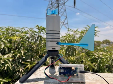
Being able to monitor the weather in real-time is great for education, research, or simply to analyze how the local climate changes over time. This project by Hackster.io user Pradeep explores how he was able to design a simple station outdoors that could communicate with a cloud-based platform for aggregating the sensed data. The board Pradeep selected is the Arduino MKR WiFi 1010 owing to its low-power SAM D21 microcontroller and Wi-Fi/BLE connectivity for easy, wireless communication. After configured, he connected a DFRobot Lark Weather Station, which contains sensors for measuring wind speed/direction, temperature, humidity, and barometric pressure — all in a compact device. Every second, the MKR WiFi 1010’s sketch polls the sensors for new data over I2C before printing it to USB. The cloud integration aspect was achieved by leveraging Qubitro’s platform to collect and store the data for later visualization and analysis. To set it up, Pradeep created a new device connection and copied the resulting MQTT endpoint/token into his sketch. Then once new data became ready, it got serialized into a JSON payload and sent to the topic where a variety of widgets could then show dials and charts of each weather-related metric. To read more about this DIY weather station, you can visit Pradeep’s project write-up here.


