


J-Link EDU Mini classroom package
Sold outSEGGER J-Link EDU Mini is a version of the SEGGER J-Link EDU debugger in a reduced form factor with identical functionality.
It has been designed to allow students and educational facilities as well as hobbyists access to top of the line debug probe technology.
Overview
Get the J-Link EDU Mini, offering the same functionality as the J-Link EDU but in a reduced form factor.
The J-Link EDU Mini Classroom Edition includes twelve J-Link EDU Mini units on special offer. Designed for education purposes and hobbyists, it provides access to top-of-the-line debug probe functionality. With a tiny form factor (18mm by 50mm, similar to a USB stick), users can enjoy full functionality.
It is JTAG and SWD supported and can only be used for non-commercial education purposes.
Other Details:
Various cores are supported by the J-Link EDU Mini. Find a complete list of supported cores here. J-Link also allows applications to access a CPU simultaneously, such as being used in parallel as a debugger. Like all SEGGER products, it is cross platform working on Windows, Linux and macOS.
Box Contents:
- 12 units of J-Link EDU mini
- 12 .05" 19-pin target cable
- 12 .05" 9-pin target cable
- 12 Micro USB cable
SEGGER J-Link debuggers are the most popular choice for optimizing the debugging and flash programming experience.
Documentation
Debugging with the Arduino IDE 2.0
Learn how to set up a Zero board, J-Link and Atmel-ICE debuggers with the Arduino IDE 2.0, and how to debug a program.
Using the Segger J-Link debugger with the MKR boards
Learn how to set up a MKR board with the Segger J-link debugger.
Get Inspired
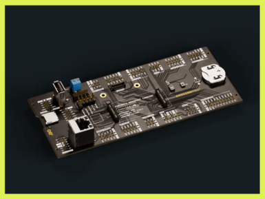
We are pleased to announce the launch of the new Arduino Portenta Breakout, designed for developing hardware projects, testing, and debugging on Portenta family boards.The Portenta Breakout exploits all the capabilities of the input and outputs, making all high density connectors’ signals individually accessible. The Portenta Breakout reduces development time for industrial grade solution automation based on the Portenta line. Designed to help the hardware engineers and makers who want to develop a proprietary device for Portenta family boards or interfacing external devices to the Portenta family boards (e.g. the Portenta H7). It is now quick and easy to connect and test external hardware components and devices in the lab using all the high density connectors’ signals of the Portenta individually. Rapid development for machine vision Connectivity to the OpenMV Global Shutter Camera Module is provided on the Portenta Breakout, allowing for rapid development of machine vision applications alongside the Portenta family. Test external hardware and devices The Portenta Breakout enables easy debugging through the JTAG connector and allows for inspection of the bus lines through the breakout pins. In addition to the breakout pins, the Portenta Breakout features Ethernet, USB and SD sockets, a coin cell, a power button, an external power supply, an OpenMV camera socket, and configurable boot selection modes. Features include: Power ON buttonBoot mode DIP switchConnectorsUSBARJ45 GBit EthernetMicroSD cardOpenMV shutter moduleMIPI 20T JTAG with trace capabilityPowerCR2032 RTC lithium battery backupExternal power terminal blockI/OBreak out all Portenta high density connector signals Male/female HD connectors for interposing breakout between Portenta and shield to debug signals Beyond use in the development lab, the Portenta Breakout can act as a first point of entry for educating technicians in industrial grade control and embedded


