


Arduino IoT Bundle
The Arduino IoT Bundle is the best way to start exploring the world of connected devices using the Arduino Nano RP2040 Connect. Follow the 5 step by step tutorials to quickly learn how to build IoT devices.
Overview
Follow the 5 step by step tutorials we have prepared for you and combining the electronic components included in the bundle, you’ll quickly learn how to build devices that connect to the Arduino IoT Cloud.
The 5 step by step tutorials are:
Arduino IoT Cloud Compatible

Tech specs
Each bundle includes:
- 1 Arduino Nano RP2040 Connect
- 1 micro USB cable
- 1 400-point breadboard
- 70 solid-core jumper wires
- 2 stranded jumper wire
- 6 phototransistors
- 3 potentiometers (10k ohm)
- 10 pushbuttons
- 1 temperature sensor (TMP36)
- 1 tilt sensor
- 1 alphanumeric LCD (16 x 2 characters)
- 1 bright white
- 28 LEDs (1 RGB, 8 red, 8 green, 8 yellow, 3 blue)
- 1 small DC motor (6/9V)
- 1 small servo motor
- 1 piezo capsule (PKM17EPP-4001-B0)
- 1 H-bridge motor driver (L293D)
- 1 optocouplers (4N35)
- 2 MOSFET transistors (IRF520)
- 5 capacitors (100uF)
- 5 diodes (1N4007)
- 1 male pin strip (40 x 1)
- 20 resistors (220 ohm)
- 5 resistors (560 ohm)
- 5 resistors (1k ohm)
- 5 resistors (4.7k ohm)
- 20 resistors (10k ohm)
- 5 resistors (1M ohm)
- 5 resistors (10M ohm)
Resources for Safety and Products
Manufacturer Information
The production information includes the address and related details of the product manufacturer.
Arduino S.r.l.
Via Andrea Appiani, 25
Monza, MB, IT, 20900
https://www.arduino.cc/
Responsible Person in the EU
An EU-based economic operator who ensures the product's compliance with the required regulations.
Arduino S.r.l.
Via Andrea Appiani, 25
Monza, MB, IT, 20900
Phone: +39 0113157477
Email: support@arduino.cc
Get Inspired
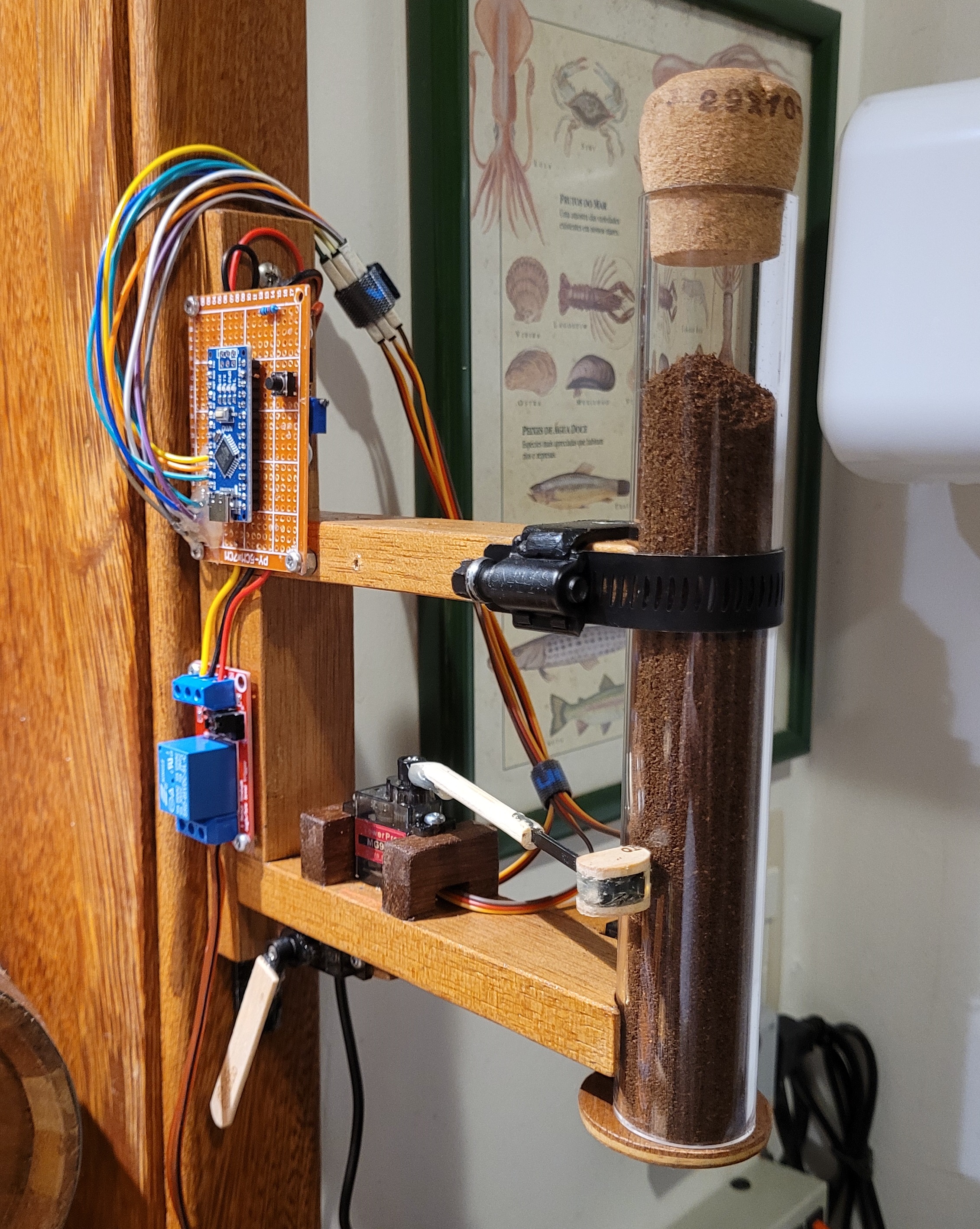
Device to automate that ordinary coffee maker everyone has.
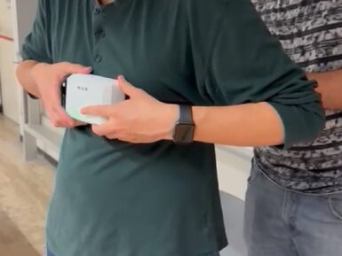
For children who experience certain developmental delays, specific types of physical therapies are often employed to assist them in improving their balance and motor skills/coordination. Ivan Hernandez, Juan Diego Zambrano, and Abdelrahman Farag were looking for a way to quantify the progress patients make while simultaneously presenting a gamified approach, so they developed a standalone node for equilibrium evaluation that could do both. On the hardware side of things, an Arduino Nano BLE 33 Sense Rev2 is responsible for handling all of the incoming motion data from its onboard BMI270 six-axis IMU and BMM150 three-axis magnetometer. New readings are constantly taken, filtered, and fused together before being sent to an external device over Bluetooth Low Energy. The board was also connected to a buzzer and buttons for user inputs, as well as an RGB LED to get a real-time status. The patient begins the session by first putting on the wearable and connecting to the accompanying therapist application. Next, a game starts in which the user must move their torso to guide an image of a shark over the image of a stationary fish within a time period — ultimately trying to get the highest score possible. Throughout all of this, a vision system synchronizes its readings with the IMU sensor readings for an ultra-detailed look at how the patient responds to the game over time. To read more about the project, you can visit the team's write-up on Hackaday.io.
FAQs
I plugged the board to my PC / MAC but I cannot see the serial port listed in the IDE, so I can't upload my sketch to the board!
- Make sure the foam that protects the boards’ pins is removed.
- Try connecting the board with another USB cable.
- Try connecting the board to another USB port. If possible, avoid USB-hubs.
You can see more information and other things to try in this Help Center article.
Do I need to subscribe to the Arduino IoT Cloud to build the projects described in the tutorials?
No, all the projects can be built using the free plan of the Arduino IoT Cloud. Click here to see what is included in the plan.
How to enable the 5V / VUSB pin?
The 5V pin is disabled by default. You can locate on the bottom of the board on the VBUS pin two pads, shorting these will enable 5V output. More info on this here.
Where can I find the step by step tutorials?
You can find the step by step tutorials at arduino.cc/iot-bundle


