


Overview
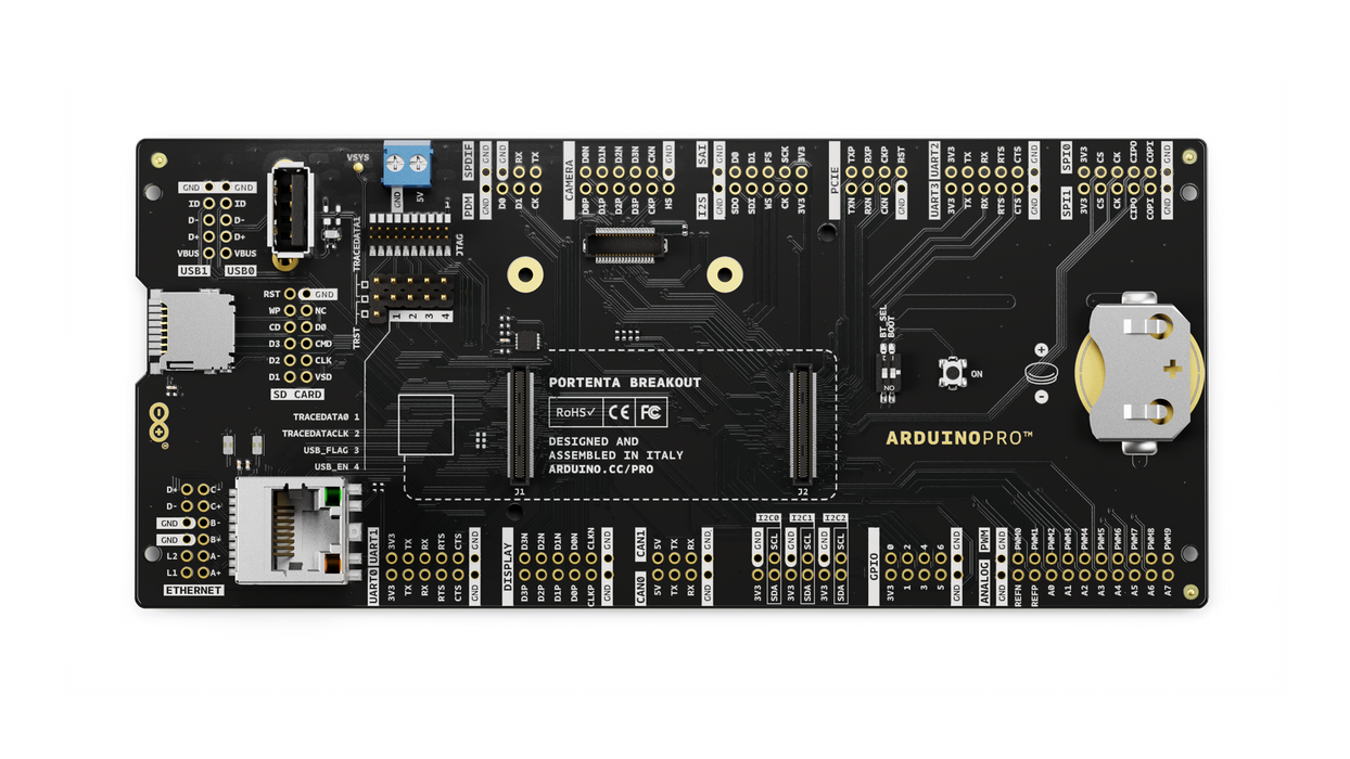
Portenta Breakout board is designed to help hardware engineers and makers to prototype and help test devices connections and capacity within the Portenta family boards (e.g. the Portenta H7).
It makes all high-density connectors’ signals individually accessible, making it quick and easy to connect and test external hardware components and devices as normally needed during development in the lab.
Target areas
Prototyping
Application examples
This product is designed to work alongside the Portenta family. Please check the Getting Started guide of your Portenta board.
Product Development: The Portenta Breakout board reduces development time for industrial grade solution automation based on the Portenta line.
Technical Education: The Portenta Breakout board can act as the first point of entry for technician education in industrial grade control and embedded systems.
Features
- Power ON Button
- Boot mode DIP switch
- Connectors
- USBA
- RJ45 up to 1Gb/s
- Micro SD card
- MIPI 20T JTAG with trace capability - Power
- CR2032 RTC Lithium Battery backup
- External power terminal block - I/O
- Break out all Portenta High Density connector signals
- Male/female HD connectors allow interposing breakout between Portenta and shield to debug signals - Compatibility
- Standard Portenta High Density connector pinout - Safety information
- Class A
Tech specs
| USB port | USBA |
| Ethernet | RJ45 up to 1Gb/s (Supported on Portenta X8 only) |
| Memory slot | Micro SD card |
| Debug | MIPI 20T JTAG with trace capability |
| Connectors | HD male/female |
| RTC power battery | CR2032 |
| Length | 164 mm |
| Width | 72 mm |
| Weight | 0,069 Kg |
Conformities
Resources for Safety and Products
Manufacturer Information
The production information includes the address and related details of the product manufacturer.
Arduino S.r.l.
Via Andrea Appiani, 25
Monza, MB, IT, 20900
https://www.arduino.cc/
Responsible Person in the EU
An EU-based economic operator who ensures the product's compliance with the required regulations.
Arduino S.r.l.
Via Andrea Appiani, 25
Monza, MB, IT, 20900
Phone: +39 0113157477
Email: support@arduino.cc
Documentation
Study how the Portenta Breakout Carrier works using following files:
Pinout Diagram
Learn more about the portenta's pinout by reading the pinout documentation.
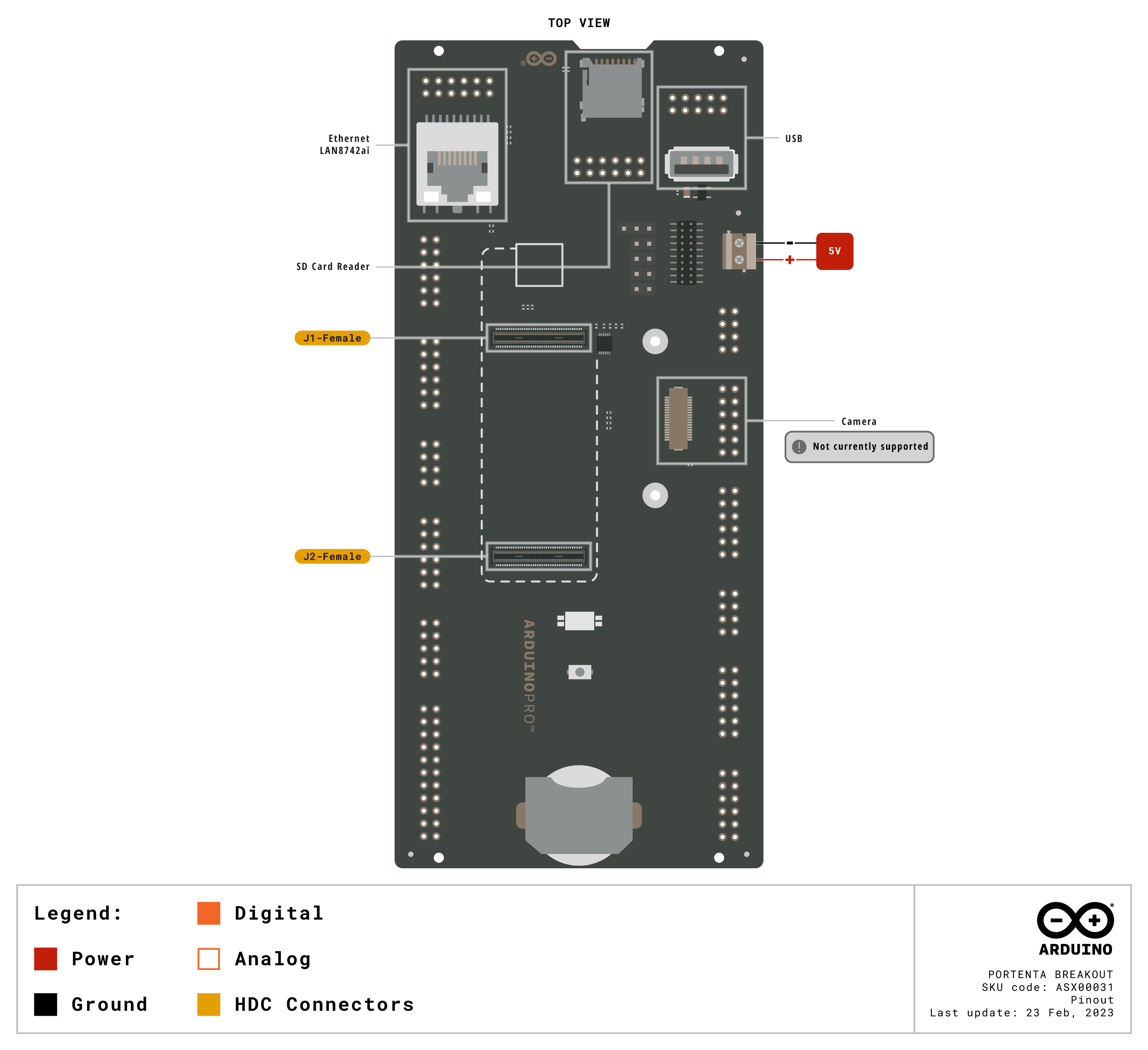
Download the full pinout diagram as PDF here.
Interactive Board Viewer
Learn more
Get Inspired
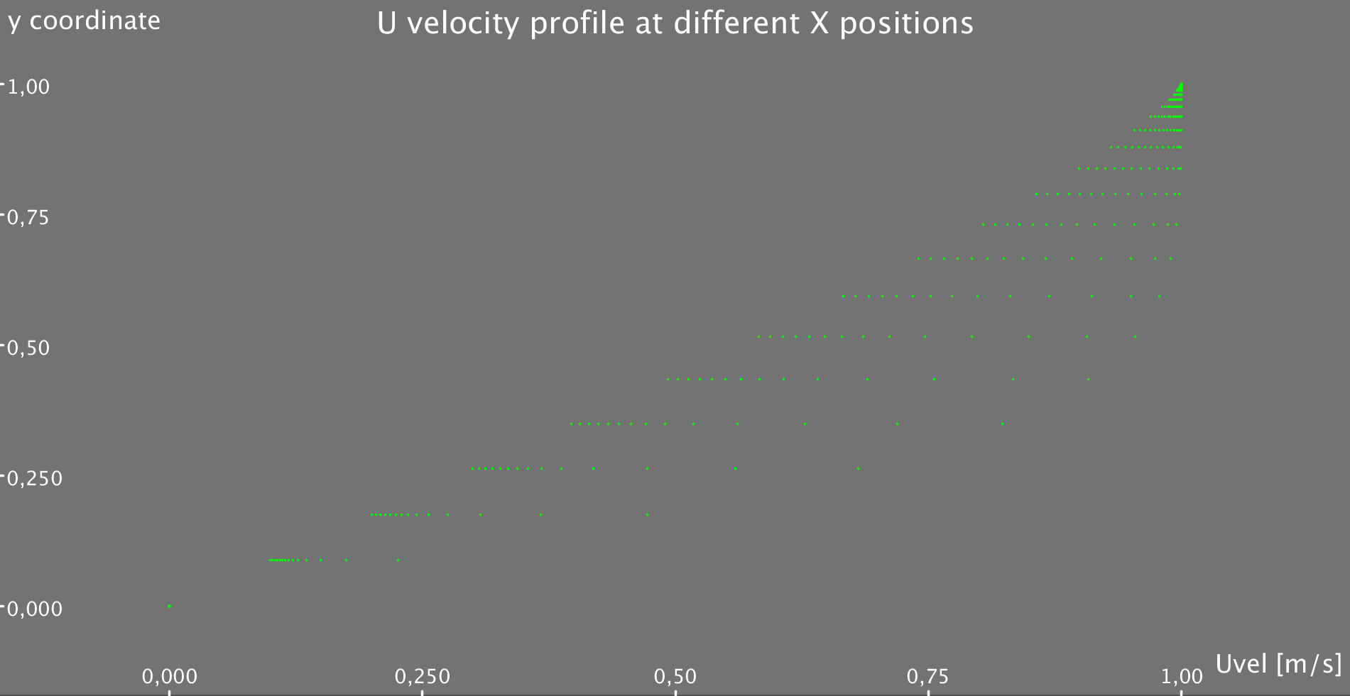
Simple Code that allows you to solve the 2D flow equation for a flat plate Boundary Layer!!
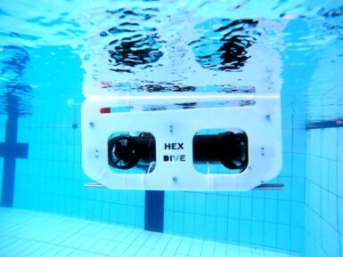
Who doesn’t want to explore underwater? To take a journey beneath the surface of a lake or even the ocean? But a remotely operated vehicle (ROV), which is the kind of robot you’d use for such an adventure, isn’t exactly the kind of thing you’ll find on the shelf at your local Walmart. You can, however, follow this guide from Ranuga Amarasinghe to build your own ROV for some aquatic fun. Amarasinghe is a 16-year-old Sri Lankan student and this is actually the second iteration of his ROV design. As such, he's dubbed it “ROV2” and it appears to be quite capable. All of its electronics sit safely within a 450mm length of sealed PVC tube. That mounts onto the aluminum extrusion frame structure that also hosts the six thrusters powered by drone-style brushless DC motors. ROV2’s brain is an Arduino Mega 2560 board and it drives the BLDC motors through six electronic speed controllers (ESCs). It receives control commands from the surface via an umbilical. The operator holds a Flysky transmitter that sends radio signals to a receiver floating on the water. An Arduino UNO Rev3 reads those and then communicates the motor commands to the Mega through the tethered serial connection. That limits the maximum length of the tether to about 40 meters, which subsequently limits the maximum operating depth. With the specified lithium battery pack, ROV2 can traverse the depths for 30-45 minutes. And when equipped with the 720p FPV camera, pilots can see and record all of the underwater action.


