


Overview
The Arduino MKR WiFi 1010 is the easiest point of entry to basic IoT and pico-network application design. Whether you are looking at building a sensor network connected to your office or home router, orif you want to create a Bluetooth® Low Energy device sending data to a cellphone, the MKR WiFi 1010 is your one-stop-solution for many of the basic IoT application scenarios.
See what Massimo Banzi, Arduino Co-founder, has to say about this board in the following video.
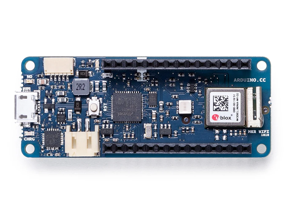
The board's main processor is a low power Arm® Cortex®-M0 32-bit SAMD21, like in the other boards within the Arduino MKR family. The WiFi and Bluetooth® connectivity is performed with a module from u-blox, the NINA-W10, a low power chipset operating in the 2.4GHz range. On top of those, secure communication is ensured through the Microchip® ECC508 crypto chip. Besides that, you can find a battery charger, and a directional RGB LED on-board.
Arduino IoT Cloud Compatible

Use your MKR board on Arduino's IoT Cloud, a simple and fast way to ensure secure communication for all of your connected Things.
TRY THE ARDUINO IOT CLOUD FOR FREE
Official Arduino WiFi Library
At Arduino we have made connecting to a WiFi network as easy as getting an LED to blink. You can get your board to connect to any kind of existing WiFi network, or use it to create your own Arduino Access Point. The specific set of examples we provide for the MKR WiFi 1010 can be consulted at the WiFiNINA library reference page.
Compatible with other Cloud Services
It is also possible to connect your board to different Cloud services, Arduino's own among others. Here some examples on how to get the MKR WiFi 1010 to connect to:
- Blynk: a simple project from our community connecting to Blynk to operate your board from a phone with little code
- IFTTT: see an in-depth case of building a smart plug connected to IFTTT
- AWS IoT Core: we made this example on how to connect to Amazon Web Services
- Azure: visit this github repository explaining how to connect a temperature sensor to Azure's Cloud
- Firebase: you want to connect to Google's Firebase, this Arduino library will show you how
Bluetooth® and Bluetooth® Low Energy
The communications chipset on the Nano 33 BLE Sense can be both a Bluetooth® Low Energy and Bluetooth® client and host device. Something pretty unique in the world of microcontroller platforms. If you want to see how easy it is to create a Bluetooth® central or a peripheral device, explore the examples at our ArduinoBLE library.
We Make it Open for you to Hack Along
The MKR WiFi 1010 is a dual processor device that invites for experimentation. Hacking the WiFiNINA module allows you to, for example, make use of both WiFi and Bluetooth® / Bluetooth® Low Energy at once on the board. Yet another possibility is having a super-lightweight version of linux running on the module, while the main microcontroller controls low level devices like motors, or screens. These experimental techniques, require advanced hacking on your side. They are possible via modifying the module's firmware that you can find at our github repositories.
BEWARE: this kind of hacking breaks the certification of your WiFiNINA module, do it at your own risk.
Battery Power
Its USB port can be used to supply power (5V) to the board. It has a Li-Po charging circuit that allows the Arduino MKR WiFi 1010 to run on battery power or an external 5 volt source, charging the Li-Po battery while running on external power. Switching from one source to the other is done automatically.
Related Boards
If you are looking at upgrading from previous Arduino designs, or if you are just interested in boards with similar functionality, at Arduino you can find:
- Arduino Uno WiFi rev2: the education version of the MKR WiFi 1010, with USB-B connector and embedded accelerometer. Read more here.
- Nano 33 IoT: if you need an even smaller form factor, this board sacrifices the battery connector, but the basic functionality is essentially the same. Visit its product page here.
- MKR WiFi 1000: can only run WiFi applications, as it includes a different chipset than the MKR WiFi 1010. Read more about it here.
Getting Started
The Getting Started section contains all the information you need to configure your board, use the Arduino Software (IDE), and start tinkering with coding and electronics.
Need Help?
Check the Arduino Forum for questions about the Arduino Language, or how to make your own Projects with Arduino. Need any help with your board please get in touch with the official Arduino User Support as explained in our Contact Us page.
Warranty
You can find here your board warranty information.
Tech specs
The Arduino MKR WiFi 1010 is based on the SAMD21 microcontroller.
| Microcontroller | SAMD21 Cortex®-M0+ 32bit low power ARM® MCU (datasheet) |
| Radio module | u-blox NINA-W102 (datasheet) |
| Board Power Supply (USB/VIN) | 5V |
| Secure Element | ATECC508 (datasheet) |
| Supported Battery | Li-Po Single Cell, 3.7V, 1024mAh Minimum |
| Circuit Operating Voltage | 3.3V |
| Digital I/O Pins | 8 |
| PWM Pins | 13 (0 .. 8, 10, 12, 18 / A3, 19 / A4) |
| UART | 1 |
| SPI | 1 |
| I2C | 1 |
| Analog Input Pins | 7 (ADC 8/10/12 bit) |
| Analog Output Pins | 1 (DAC 10 bit) |
| External Interrupts | 10 (0, 1, 4, 5, 6, 7, 8,9, 16 / A1, 17 / A2) |
| DC Current per I/O Pin | 7 mA |
| CPU Flash Memory | 256 KB (internal) |
| SRAM | 32 KB |
| EEPROM | no |
| Clock Speed | 32.768 kHz (RTC), 48 MHz |
| LED_BUILTIN | 6 |
| USB | Full-Speed USB Device and embedded Host |
| Length | 61.5 mm |
| Width | 25 mm |
| Weight | 32 gr. |
Conformities
Resources for Safety and Products
Manufacturer Information
The production information includes the address and related details of the product manufacturer.
Arduino S.r.l.
Via Andrea Appiani, 25
Monza, MB, IT, 20900
https://www.arduino.cc/
Responsible Person in the EU
An EU-based economic operator who ensures the product's compliance with the required regulations.
Arduino S.r.l.
Via Andrea Appiani, 25
Monza, MB, IT, 20900
Phone: +39 0113157477
Email: support@arduino.cc
Documentation
OSH: Schematics
The MKR WiFi 1010 is open-source hardware! You can build your own board using the following files:
EAGLE FILES IN .ZIP SCHEMATICS IN .PDFDATASHEET IN .PDFFRITZING IN .FZPZ
Pinout Diagram
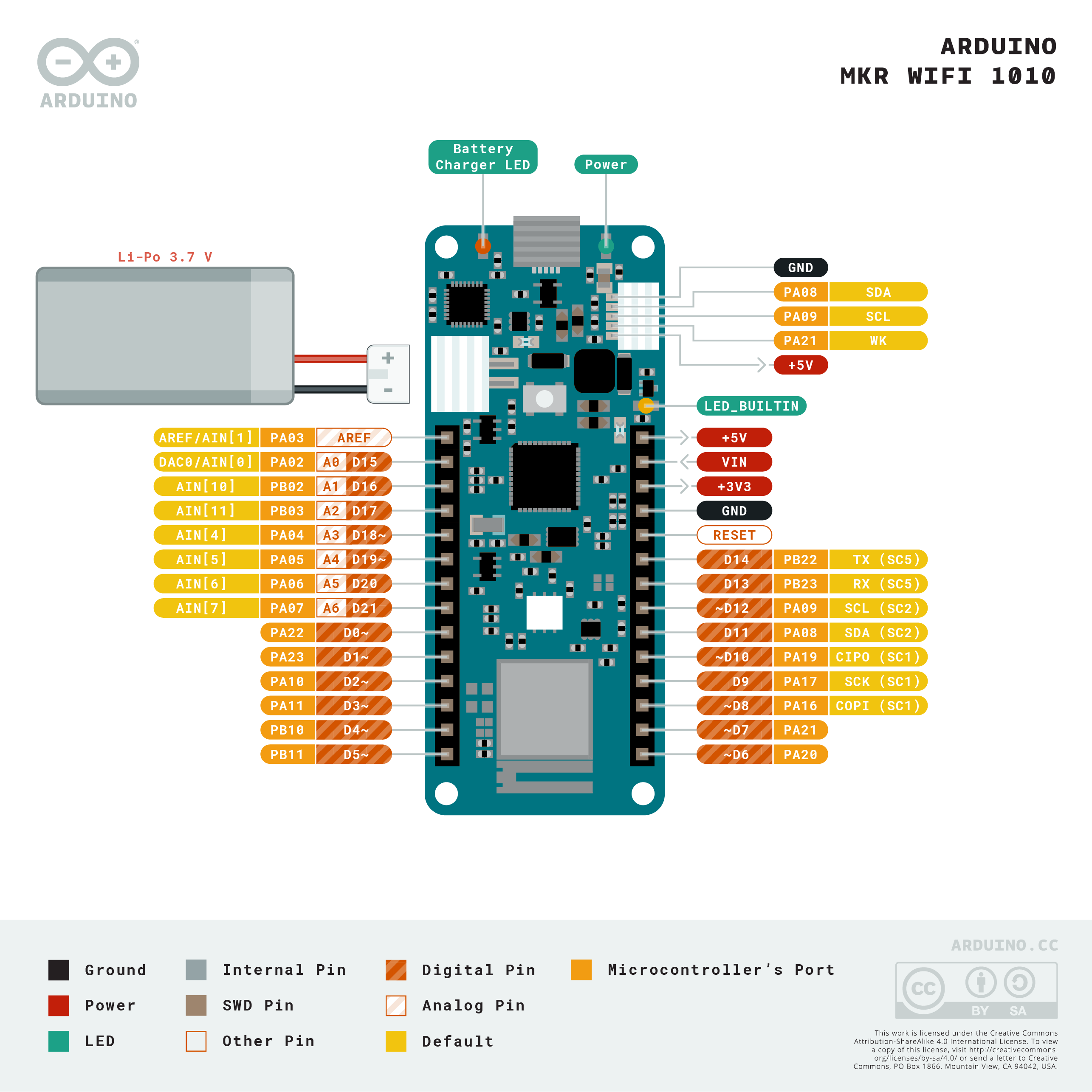
Download the full pinout diagram as PDF here.
Interactive Board Viewer
Additional I2C Port
The MKR WiFi 1010 has an additional connector meant as an extension of the I2C bus. It's a small form factor 5-pin connector with 1.0 mm pitch. The mechanical details of the connector can be found in the connector's datasheet.
The I2C port, also referred to as the Eslov self-identification port within Arduino, comes with: SDA, SCL, GND, +5V, and an extra digital pin meant to send an alarm to the otherwise plain I2C devices connected to it. The pinout is shown in the following image:

If you are interested in designing your own modules for Arduino boards with this expansion port, the connector we suggest using is code: SHR-05V-S-B, also in the picture.
Learn more
Get Inspired
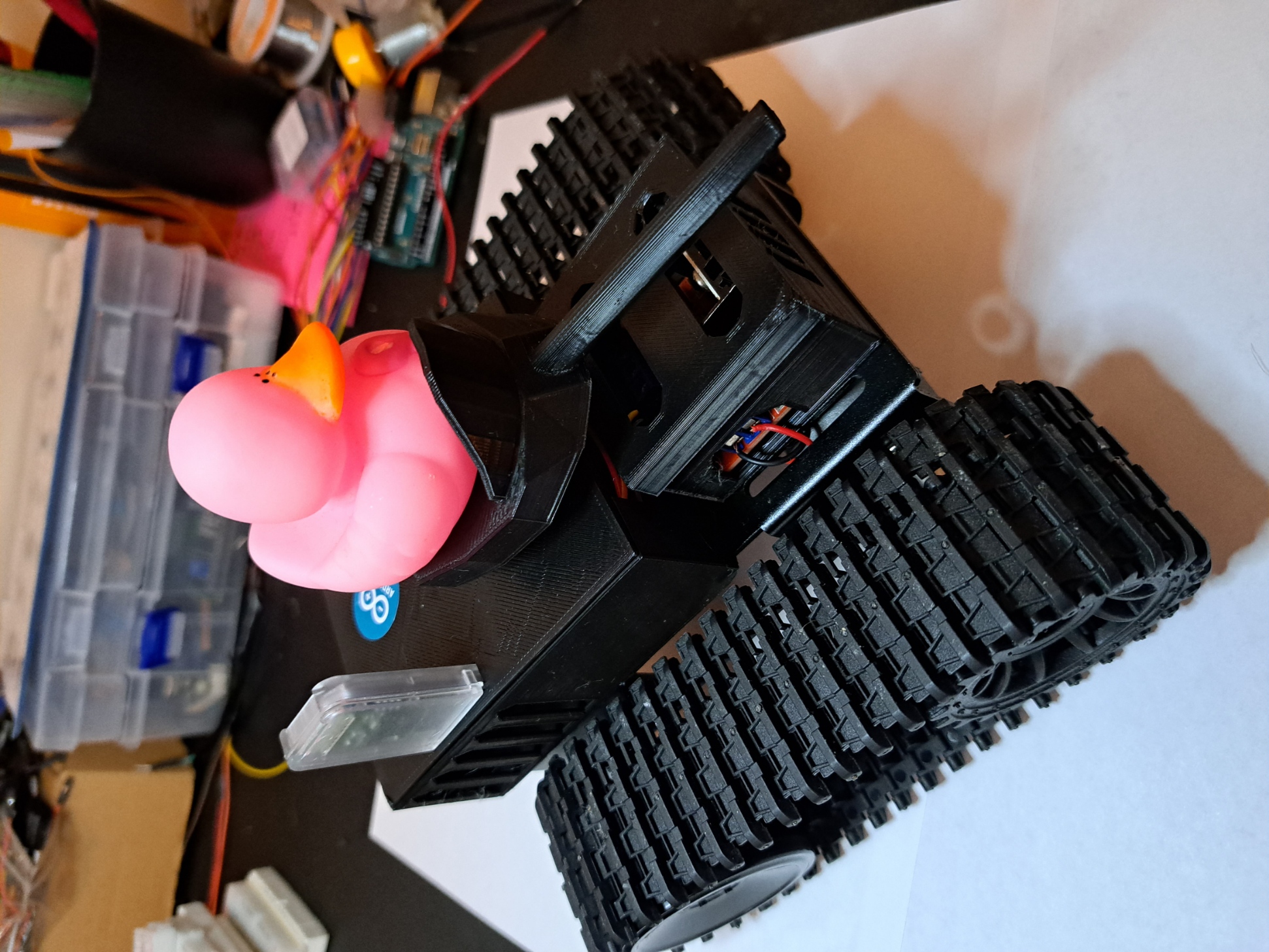
I'm excited to share the details of my BT Arduino Tank project, which incorporates some impressive 3D-printed components. While the main chassis of the tank was not 3D-printed, I utilized this technology to create two crucial parts: the enclosure for the motor driver and the compartment housing the remaining electronics. Additionally, I 3D-printed a cannon for an added touch of customization. The enclosure for the motor driver served as a protective housing, ensuring that the L298N motor driver module was securely mounted and shielded from external elements. By designing and 3D-printing this part, I could precisely fit it to the tank's specifications, providing a neat and organized arrangement of the electronics. In the same vein, the compartment for the remaining electronics, such as the Arduino Nano Every and the HC-05 Bluetooth module, was also 3D-printed. This enclosure offered a clean and organized solution for housing these components, safeguarding them while maintaining easy access for maintenance or modifications. Lastly, to enhance the tank's appearance and add a touch of personalization, I designed and 3D-printed a cannon. This custom-printed cannon perfectly complemented the overall design, making the tank even more visually appealing. By strategically incorporating 3D printing into specific parts of the project, I achieved a balance between functionality and customization. The precision and versatility of 3D printing allowed me to create tailored enclosures and a unique cannon, elevating the overall aesthetic and practicality of my BT Arduino Tank project.
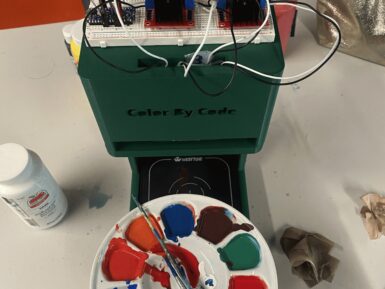
When you want to paint the walls in your bedroom that very specific shade of Misty Irish Green, all you have to do is head to your local hardware store and have them scan the corresponding card. The paint-mixing machine will then add the pigment to a white base and, a few minutes later, you have that exact color. So, shouldn’t you be able to do the same thing with acrylic paint for hobby purposes? Now you can, thanks to the “Color By Code” machine designed by Caltech students Frida Moreno and Asmat Kaur Taunque. Moreno and Taunque built Color By Code for a class project and it is, essentially, a hobby version of those hardware store paint-mixers intended for acrylic paint. As is the standard across many industries that deal with pigments, paint, and printing, this works using CMYK (cyan, magenta, yellow, key) color mixing. Here, the key is black and the machine takes an input color value for each component, then dispenses the paint in those ratios to achieve the desired hue. That all happens under the control of an Arduino Nano Every board. That operates peristaltic pumps, via L298N motor drivers, that dispense each color. Afterwards, a flushing procedure clears the lines before the next mix. The pumps fit into a 3D-printed stand, with the hoses dropping below to a waiting container. At this time, the user must set the color values through serial commands. But the team hopes to create a Bluetooth app in the future. They also plan to add a weight sensor, which would improve the machine’s accuracy.
FAQs
Batteries, Pins and board LEDs
- Battery capacity: rechargeable Li-Ion, or Li-Po. Please make sure the battery connector suits your battery.
- Battery connector: The connector is of type JST S2B-PH-SM4-TB(LF)(SN). Mating connector is JST PHR-2.
- Vin: This pin can be used to power the board with a regulated 5V source. If the power is fed through this pin, the USB power source is disconnected. This is the only way you can supply 5v (range is 5V to maximum 6V) to the board not using USB. This pin is an INPUT.
- 5V: This pin outputs 5V from the board when powered from the USB connector or from the VIN pin of the board. It is unregulated and the voltage is taken directly from the inputs.
- VCC: This pin outputs 3.3V through the on-board voltage regulator. This voltage is 3.3V if USB or VIN is used and equal to the series of the two batteries when they are used
- LED ON: This LED is connected to the 5V input from either USB or VIN. It is not connected to the battery power, thus minimizing the impact on battery usage. It is therefore normal to have the board properly running on battery power without the LED ON being lit.
- Onboard LED: On MKR WAN 1010 the onboard LED is connected to D6.


