


Overview
The Arduino 4 Relays Shield is a solution for driving high power loads that cannot be controlled by Arduino's digital IOs, due to the current and voltage limits of the controller. The Shield features four relays, each relay provides 2 pole changeover contacts (NO and NC); in order to increase the current limit of each output the 2 changeover contacts have been put in parallel. Four LEDs indicate the on/off state of each relay.
Getting Started
You can find in the Getting Started section all the information you need to configure your board, use the Arduino Software (IDE), and start tinker with coding and electronics..
Need Help?
- On the Software on the Arduino Forum
- On Projects on the Arduino Forum
- On the Product itself through our Customer Support
Tech specs
Features
| Thinker Kit interface | 2x TWI, 2x OUT, 2x IN |
| Interfaces with Arduino Board | DIO |
| Relays | 4 (60W) |
General
| Operating Voltage | 5 V |
| Current needs | 140 mA (with all releays on, about 35 mA each) |
| PCB Size | 53 x 68.5 mm |
| Weight | 0.044 Kg |
| Product Code | A000110 |
Conformities
Resources for Safety and Products
Manufacturer Information
The production information includes the address and related details of the product manufacturer.
Arduino S.r.l.
Via Andrea Appiani, 25
Monza, MB, IT, 20900
https://www.arduino.cc/
Responsible Person in the EU
An EU-based economic operator who ensures the product's compliance with the required regulations.
Arduino S.r.l.
Via Andrea Appiani, 25
Monza, MB, IT, 20900
Phone: +39 0113157477
Email: support@arduino.cc
Documentation
OSH: Schematics
The Arduino 4 Relays Shield is open-source hardware! You can build your own board using the following files:
EAGLE FILES IN .ZIP SCHEMATICS IN .PDF
Description
|
Operating Voltage |
5V |
|
Coil current consumption |
140 mA (with all releays on, about 35 mA each) |
|
Single pole chargeover contact maximum current |
@ 30 V DC 2A |
|
Maximum load voltage |
48 V |
|
Maximum switching capacity |
60 W |
Power
The shield doesn't need external power: it will be provided by the base board, through the 5V and 3.3V pins of the Arduino board used as base.
Input and Output
The relays are controlled by the following Arduino board pins: Relay 1 = Arduino pin 4 Relay 2 = Arduino pin 7 Relay 3 = Arduino pin 8 Relay 4 = Arduino pin 12 The shield features several TinkerKit input/output and communication interfaces. Connecting TinkerKit modules can simplify the creation of a project or a prototype. The on-board connectors are :
- 2 TinkerKit Inputs: IN2 and IN3 (in white), these connectors are routed to the Arduino A2 and A3 analog input pins.
- 2 TinkerKit Outputs: OUT5 and OUT6 (in orange), these connectors are routed to the Arduino PWM outputs on pins 5 and 6.
- 2 TinkerKit TWI: these connectors (4-pin in white) are routed on the Arduino TWI interface. Both connect to the same TWI interface to allow you to create a chain of TWI devices.
Physical Characteristics
The maximum length and width of the 4 Relays Shield PCB are 2.7 and 2.1 inches respectively. Four screw holes allow the Shield to be attached to a surface or case. Note that the distance between digital pins 7 and 8 is 160 mil (0.16"), not an even multiple of the 100 mil spacing of the other pins.
Compatible Boards
The shield is compatible with all the Arduino boards, 5V and also 3.3V standards.
Learn more
Get Inspired

Control the air/fuel mixture for a better fuel economy of a engine with a Arduino Nano.
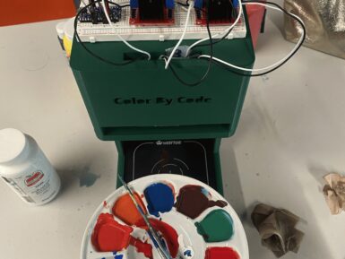
When you want to paint the walls in your bedroom that very specific shade of Misty Irish Green, all you have to do is head to your local hardware store and have them scan the corresponding card. The paint-mixing machine will then add the pigment to a white base and, a few minutes later, you have that exact color. So, shouldn’t you be able to do the same thing with acrylic paint for hobby purposes? Now you can, thanks to the “Color By Code” machine designed by Caltech students Frida Moreno and Asmat Kaur Taunque. Moreno and Taunque built Color By Code for a class project and it is, essentially, a hobby version of those hardware store paint-mixers intended for acrylic paint. As is the standard across many industries that deal with pigments, paint, and printing, this works using CMYK (cyan, magenta, yellow, key) color mixing. Here, the key is black and the machine takes an input color value for each component, then dispenses the paint in those ratios to achieve the desired hue. That all happens under the control of an Arduino Nano Every board. That operates peristaltic pumps, via L298N motor drivers, that dispense each color. Afterwards, a flushing procedure clears the lines before the next mix. The pumps fit into a 3D-printed stand, with the hoses dropping below to a waiting container. At this time, the user must set the color values through serial commands. But the team hopes to create a Bluetooth app in the future. They also plan to add a weight sensor, which would improve the machine’s accuracy.


