Overview
The Nano Every is Arduino’s 5V compatible board in the smallest available form factor: 45x18mm!
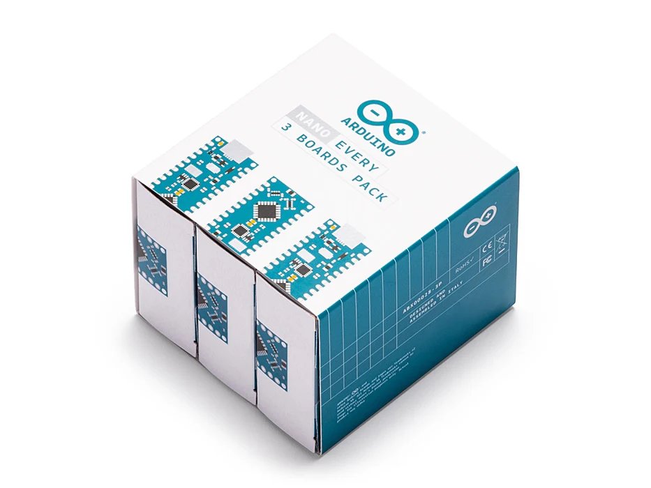
The Arduino Nano is the preferred board for many projects requiring a small and easy to use microcontroller board. One example is low cost robotics, where the Nano is broadly used. If you are in the situation of needing many boards for your classroom, or if you need to present a complex prototype with many functional blocks, this pack will offer you exactly what you need: a series of Arduino Nano Every boards at a discounted price.
The Arduino Nano Every is an evolution of the traditional Arduino Nano, but featuring a lot more powerful processor, the ATMega4809. This will allow you making larger programs than with the Arduino Uno (it has 50% more program memory), and with a lot more variables (the RAM is 200% bigger).
The pack is available in two sizes with either 3 or 6 boards of Arduino Nano Every without headers. Whether you want to minimize the size of your prototypes or share the joy of electronics with your friends, this is the best option you will find.
Get to Know More
To know more about the history of the Nano Every don’t miss the interview with Dario Pennisi, Arduino’s hardware and firmware development manager, who led the development of this board.
Getting Started
The Getting Started section contains all the information you need to configure your board, use the Arduino Software (IDE), and start tinkering with coding and electronics.
Need Help?
Check the Arduino Forum for questions about the Arduino Language, or how to make your own . For any issues when acquiring products at the Arduino store, contact our Store Customer Support. If you purchased the Nano Every Pack and found any issues get in touch with the Official Arduino User Support as explained at our Contact Page.
Warranty
You can find here your board warranty information.
Tech specs
The Arduino Nano Every is based on the ATMega4809 microcontroller.
| Microcontroller | ATMega4809 (datasheet) |
| Operating Voltage | 5V |
| Input Voltage (limit) | 21V |
| DC Current per I/O Pin | 20 mA |
| DC Current for 3.3V Pin | 50 mA |
| Clock Speed | 20MHz |
| CPU Flash Memory | 48KB (ATMega4809) |
| SRAM | 6KB (ATMega4809) |
| EEPROM | 256byte (ATMega4809) |
| PWM Pins | 5 (D3, D5, D6, D9, D10) |
| UART | 1 |
| SPI | 1 |
| I2C | 1 |
| Analog Input Pins | 8 (ADC 10 bit) |
| Analog Output Pins | Only through PWM (no DAC) |
| External Interrupts | all digital pins |
| LED_BUILTIN | 13 |
| USB | Uses the ATSAMD11D14A (datasheet) |
| Length | 45 mm |
| Width | 18 mm |
| Weight | 5 gr (with headers) |
Conformities
Resources for Safety and Products
Manufacturer Information
The production information includes the address and related details of the product manufacturer.
Arduino S.r.l.
Via Andrea Appiani, 25
Monza, MB, IT, 20900
https://www.arduino.cc/
Responsible Person in the EU
An EU-based economic operator who ensures the product's compliance with the required regulations.
Arduino S.r.l.
Via Andrea Appiani, 25
Monza, MB, IT, 20900
Phone: +39 0113157477
Email: support@arduino.cc
Documentation
OSH: Schematics
The Arduino Nano Every is open-source hardware! You can build your own board using the following files:
EAGLE FILES IN .ZIP SCHEMATICS IN .PDF
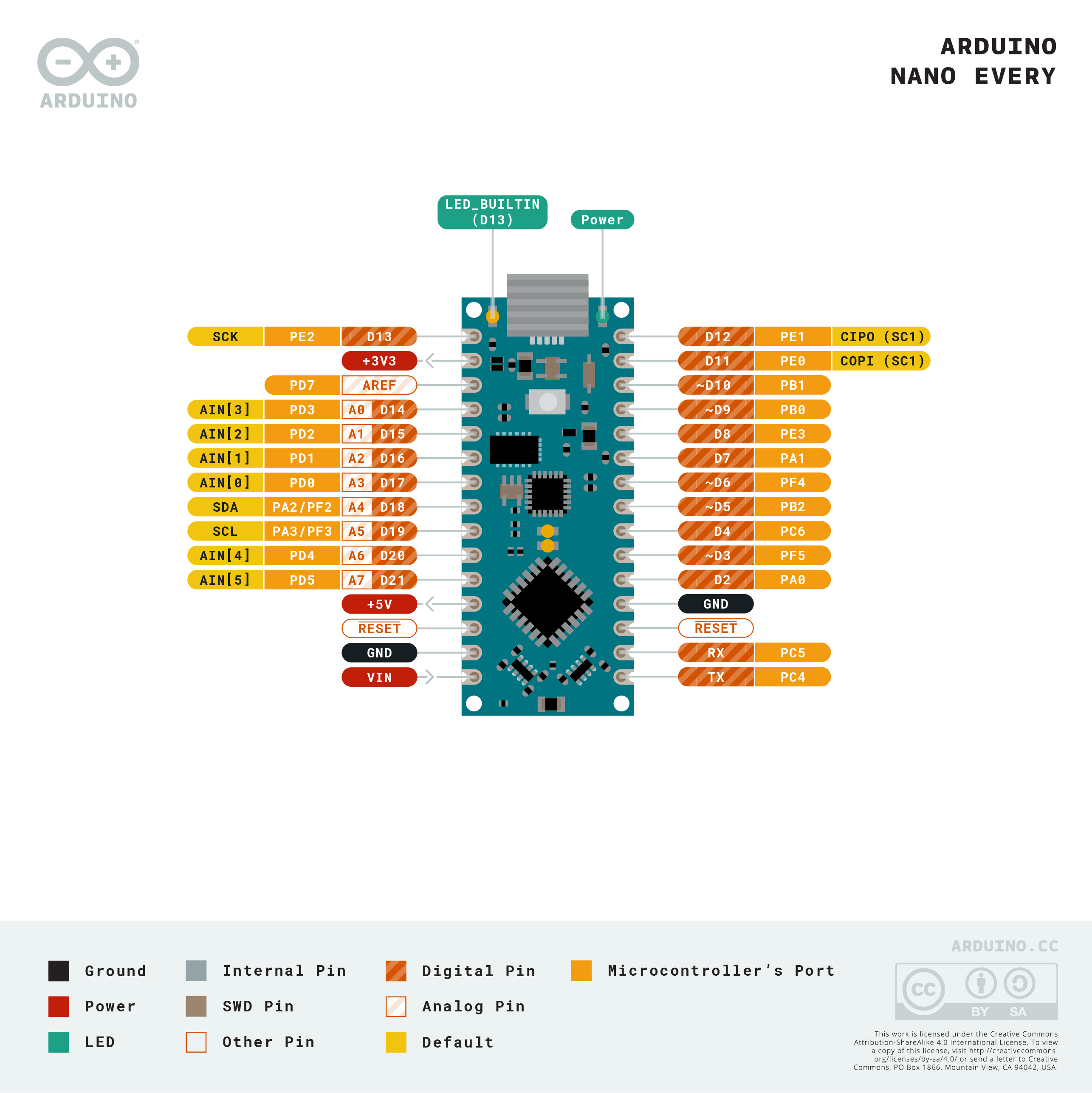
Pinout Diagram

Download the full pinout diagram as PDF here.
Download the Fritzing file here.
Learn more
Get Inspired

We are pleased to announce the launch of the new Arduino Portenta Breakout, designed for developing hardware projects, testing, and debugging on Portenta family boards.The Portenta Breakout exploits all the capabilities of the input and outputs, making all high density connectors’ signals individually accessible. The Portenta Breakout reduces development time for industrial grade solution automation based on the Portenta line. Designed to help the hardware engineers and makers who want to develop a proprietary device for Portenta family boards or interfacing external devices to the Portenta family boards (e.g. the Portenta H7). It is now quick and easy to connect and test external hardware components and devices in the lab using all the high density connectors’ signals of the Portenta individually. Rapid development for machine vision Connectivity to the OpenMV Global Shutter Camera Module is provided on the Portenta Breakout, allowing for rapid development of machine vision applications alongside the Portenta family. Test external hardware and devices The Portenta Breakout enables easy debugging through the JTAG connector and allows for inspection of the bus lines through the breakout pins. In addition to the breakout pins, the Portenta Breakout features Ethernet, USB and SD sockets, a coin cell, a power button, an external power supply, an OpenMV camera socket, and configurable boot selection modes. Features include: Power ON buttonBoot mode DIP switchConnectorsUSBARJ45 GBit EthernetMicroSD cardOpenMV shutter moduleMIPI 20T JTAG with trace capabilityPowerCR2032 RTC lithium battery backupExternal power terminal blockI/OBreak out all Portenta high density connector signals Male/female HD connectors for interposing breakout between Portenta and shield to debug signals Beyond use in the development lab, the Portenta Breakout can act as a first point of entry for educating technicians in industrial grade control and embedded
FAQs
Batteries, Pins and board LEDs
- Batteries: the Nano Every has no battery connector, nor charger. You can connect any external battery of your liking as long as you respect the voltage limits of the board.
- Vin: This pin can be used to power the board with a DC voltage source. If the power is fed through this pin, the USB power source is disconnected. This pin is an INPUT. Respect the voltage limits to assure the proper functionality of the board.
- 5V: This pin outputs 5V from the board when powered from the USB connector or from the VIN pin of the board.
- 3.3V: This pin outputs 3.3V through the on-board voltage regulator.
- LED ON: This LED is connected to the 5V input from either USB or VIN.


