


Overview
Introduction
The Education Shield is a custom-made shield designed by Arduino Education, specially tailored for educational purposes to enable quick and easy learning while building projects. The shield is meant to be used in conjuction with the CTC Program. It connects to an Arduino 101 or UNO and extend their capabilities. The shield has a collection of features that make building small projects in or outside of the classroom easy:
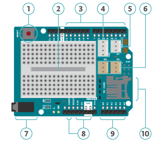
- Reset button. When this is pressed the program uploaded to the control board is restarted.
- Built in protoshield or used as a placement of breadboard.
- Digital input and output pins. Directly connected to the digital pins on the board.
- I2C connector.
- A1 3-pin header port: Analog out/in. This can also be used as a digital in/out.
- D6 and D9: digital 3-pin header ports connected to digital pin 6 and 9.
- Speaker plug:This is connected to digital pin 11.
- Ground and power pins. The voltage supply pin used in CTC is the IOREF pin. This pin outputs different voltages depending on the board (101 board: 3.3V, UNO board: 5V).
- Analog input/output pins.
- SD card reader/writer connected to digital pins 10 to 13.
Note:
- Avoid using analog A4 and A5. These have pull-up resistors connected to them and you should avoid using unless you know what you are doing.
- Do not use digital pins 4, 10, 11, 12 and 13 when using the micro SD card reader.
- Digital pins 9 to 13 cannot be used for capacitive sensors, these are connected to the SD card reader which has resistors and might therefore provide false readings.
- Digital pin 6, 9 and analog pin A1 are connected to component module ports. If the ports are used don’t use the corresponding pins.
- Digital pin 11 is connected to the audio socket. If the socket is in use don't use the pin.
Use Modules with simple connectors
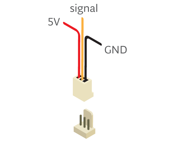
A simple 3 pin connector, that snaps in place, is used for all 3-pin modules. Here are some examples of components All these make connecting and prototyping easier through their simplified design: Push button modules, light sensor modules, and power LED modules.
If you’re trying to connect servos or other 3-pin modules, be sure about the direction of the connector so that GND is connected to GND, power to power and signal to signal. The color of a simple connector wire helps you remember it: red means power, orange or white means signal, and black means GND. Technically you can connect modules with simple connectors without 3-pin ports, as long as you plug the wires to the right pins.
Tech specs
|
Connectors |
1x I2C 4-pin connector* 1x 3-pin analog connector* 2x digital 3-pin connector* 1x pwm audiojack Plus extensions of the pins from the board. *Sullins Connector Solutions SWR25X series connector, commonly called “tinkerkit” connector” |
|
Interfaces with Arduino Board |
DIO |
|
Operating Voltage |
3.3 V (Arduino 101) or 5 V (Arduino Uno) |
|
PCB Size |
53 x 71.2 mm |
Conformities
Resources for Safety and Products
Manufacturer Information
The production information includes the address and related details of the product manufacturer.
Arduino S.r.l.
Via Andrea Appiani, 25
Monza, MB, IT, 20900
https://www.arduino.cc/
Responsible Person in the EU
An EU-based economic operator who ensures the product's compliance with the required regulations.
Arduino S.r.l.
Via Andrea Appiani, 25
Monza, MB, IT, 20900
Phone: +39 0113157477
Email: support@arduino.cc
Documentation
OSH: Schematics
The Arduino Education Shield is open-source hardware! You can build your own board using the following files:
Get Inspired

… storage save us? The smart storage solution Khairul decided to fix the problem by building his very own smart pantry, designed to keep track of ingredients and make sure nothing ever runs out. The project works by monitoring every item in the pantry, and if something is running low, it automatically orders a replacement using Amazon DRS. This project is a great way to remove human error from the process of keeping our cupboards stocked. The best part is it’s easy to do yourself at home with just a few simple components and tools. Check out the full project and instructions here. Smart wardrobe An overflowing wardrobe is a good thing — it allows you to mix up your outfits and dress well whatever the occasion. However, packed wardrobes can also be tricky to manage, and it’s easy to lose track of clothes or end up filling space with items we no longer wear. Arduino user Tan See Youu decided to fix this problem by building his own smart wardrobe. The challenge People today own more clothes than ever before. However, you probably won’t wear all of them. Over time, certain outfits tend to get forgotten and fall back into the murky depths of the wardrobe, never to see the light of day again. In areas with high humidity and warm climates like Singapore, clothes that are left for a long time in the wardrobe can even become moldy. The smart storage solution Tan See Youu’s smart wardrobe helps you manage your clothes and keep track of where everything is, displaying this information on a smart screen. The wardrobe can also push this data into the cloud and share it with your phone via a mobile application. The app can even provide suggestions on what to wear today based on the events in your calendar and the current weather forecast, and it comes with a dashboard showing which clothes you wear most frequently and which outfits you have neglected. If you haven’t worn a certain item in a while, the app can offer suggestions for


