


Overview
The Arduino Ethernet Shield 2 connects your Arduino to the internet in mere minutes. Just plug this module onto your Arduino Board, connect it to your network with an RJ45 cable (not included) and follow a few simple steps to start controlling your world through the internet. As always with Arduino, every element of the platform – hardware, software and documentation – is freely available and open-source. This means you can learn exactly how it's made and use its design as the starting point for your own circuits. Hundreds of thousands of Arduino Boards are already fueling people’s creativity all over the world, everyday. Join us now, Arduino is you!
*Requires an Arduino Board (not included)
- Operating voltage 5V (supplied from the Arduino Board)
- Ethernet Controller: W5500 with internal 32K buffer
- Connection speed: 10/100Mb
- Connection with Arduino on SPI port
You can find your board warranty information here.
Getting Started
In the Getting Started section, you can find all the information you need to configure your board, use the Arduino Software (IDE), and start to tinker with coding and electronics.
Need Help?
- Learn more on the Ethernet Shield 2 in the Ethernet2 Library reference
- Get assistance with your projects in the Arduino Forum
- Contact us through our Customer Support
Tech specs
The Arduino Ethernet Shield 2 allows an Arduino Board to connect to the internet. It is based on the (Wiznet W5500 Ethernet chip). The Wiznet W5500 provides a network (IP) stack capable of both TCP and UDP. It supports up to eight simultaneous socket connections. Use the Ethernet library to write sketches that connect to the Internet using the Shield. The Ethernet Shield 2 connects to an Arduino Board using long wire-wrap headers extending through the Shield. This keeps the pin layout intact and allows another Shield to be stacked on top of it.
The most recent revision of the board exposes the 1.0 pinout on rev 3 of the Arduino UNO Board.
The Ethernet Shield 2 has a standard RJ-45 connection, with an integrated line transformer and Power over Ethernet enabled.
There is an onboard micro-SD card slot, which can be used to store files for serving over the network. It is compatible with the Arduino Uno and Mega (using the Ethernet library). The onboard micro-SD card reader is accessible through the SD Library. When working with this library, SS is on Pin 4. The original revision of the Shield contained a full-size SD card slot; this is not supported.
The Shield also includes a reset controller, to ensure that the W5500 Ethernet module is properly reset on power-up. Previous revisions of the Shield were not compatible with the Mega and needed to be manually reset after power-up. The current Shield supports a Power over Ethernet (PoE) module designed to extract power from a conventional twisted pair Category 5 Ethernet cable.
PoE module features as follows:
- IEEE802.3af compliant
- Input voltage range 36V to 57V
- Overload and short-circuit protection
- 12V Output
- High efficiency DC/DC converter: typ 85% @ 80% load
- 1500V isolation (input to output)
NB: the Power over Ethernet module is proprietary hardware not made by Arduino, it is a third party accessory. For more information, see the datasheet
The Shield does not come with a built in PoE module, it is a separate component that must be added on. Arduino communicates with both the W5500 and SD card using the SPI bus (through the ICSP header). This is on digital pins 10, 11, 12, and 13 on the Uno and pins 50, 51, and 52 on the Mega. On both boards, pin 10 is used to select the W5500 and pin 4 for the SD card. These pins cannot be used for general I/O. On the Mega, the hardware SS pin, 53, is not used to select either the W5500 or the SD card, but it must be kept as an output or the SPI interface won't work.
Note that because the W5500 and SD card share the SPI bus, only one at a time can be active. If you are using both peripherals in your program, this should be taken care of by the corresponding libraries. If you're not using one of the peripherals in your program, however, you'll need to explicitly deselect it. To do this with the SD card, set pin 4 as an output and write a high to it. For the W5500, set digital pin 10 as a high output.
- The Shield provides a standard RJ45 Ethernet jack.
- The reset button on the Shield resets both the W5500 and the Arduino Board.
- The Shield contains a number of information LEDs:
- ON: indicates that the Board and Shield are powered
- 13 is the Arduino standard built in LED
- ACT: flashes when RX or TX activity is present
- LINK: indicates the presence of a network link and flashes when the Shield transmits or receives data
In this picture below we have tagged the yellow ACT, the green LINK,, the 13 Built in LED and the ON LED.

This shield also hosts Tinkerkit compatible connectors as follows:
- 2 TinkerKit connectors for two Analog Inputs (in white), connected to A2 and A3.
- 2 TinkerKit connectors for two Aanlog Outputs (in orange in the middle), connected to PWM outputs on pins D5 and D6.
- 2 TinkerKit connectors for the TWI interface (in white with 4 pins), one for input and the other one for output.
Conformities
Resources for Safety and Products
Manufacturer Information
The production information includes the address and related details of the product manufacturer.
Arduino S.r.l.
Via Andrea Appiani, 25
Monza, MB, IT, 20900
https://www.arduino.cc/
Responsible Person in the EU
An EU-based economic operator who ensures the product's compliance with the required regulations.
Arduino S.r.l.
Via Andrea Appiani, 25
Monza, MB, IT, 20900
Phone: +39 0113157477
Email: support@arduino.cc
Documentation
OSH: Schematics
Arduino Ethernet Shield 2 is open-source hardware! You can build your own board using the following files:
EAGLE FILES IN .ZIP SCHEMATICS IN .PDF
Previous Version
Do you own a past version of this product? Check the Arduino Ethernet Shield V1 product page.
Get Inspired
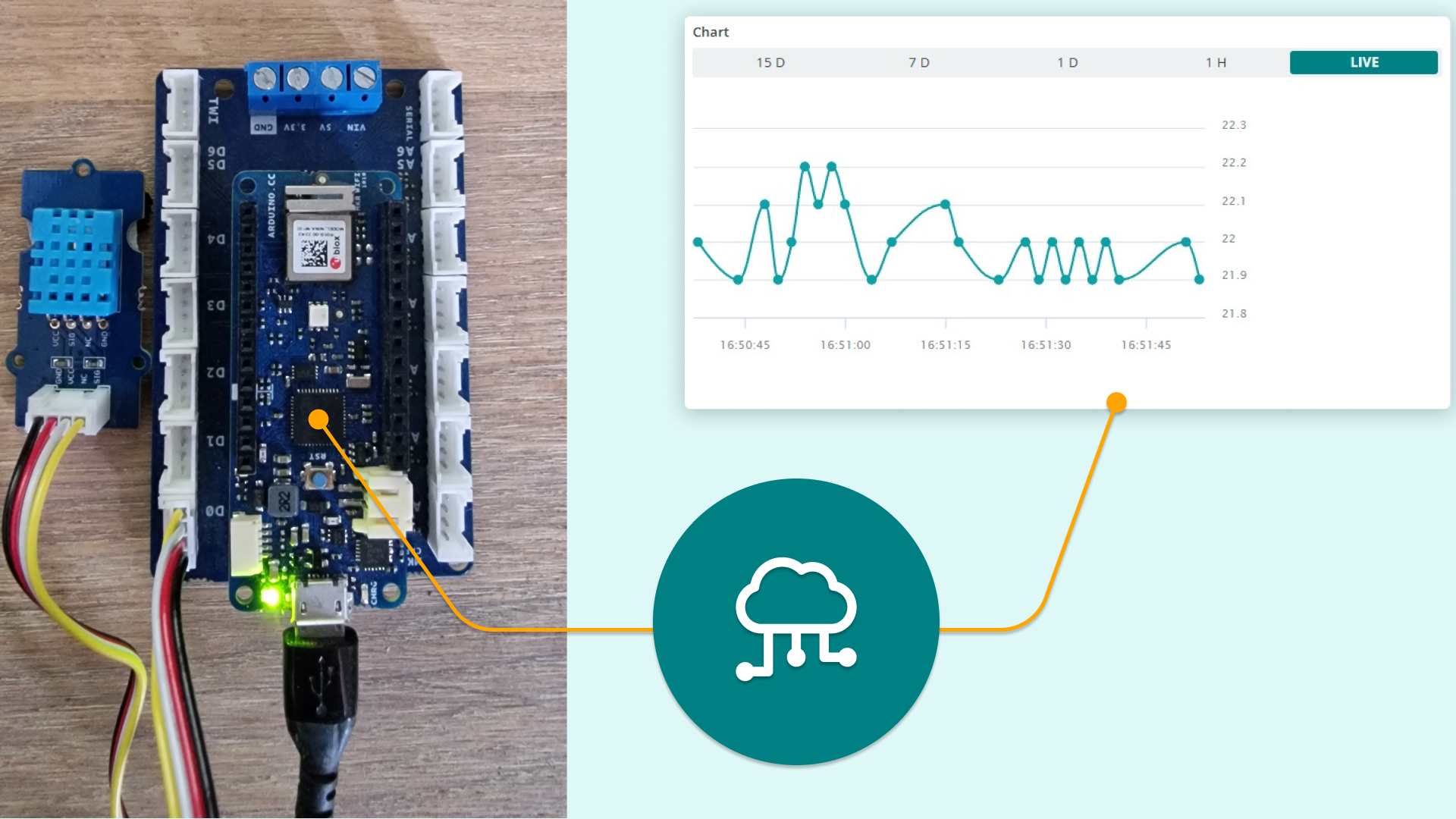
Easy data logging with grove sensors using the MKR Connector Carrier and MKR boards
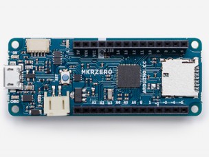
Say hello to the newest member of the Arduino family! The MKRZero--now available on our stores at the price of $21.90/€20.90 (+ tax)--shrinks the functionality of the Arduino Zero down into an Arduino MKR1000 form factor, making it a great educational tool for learning about 32-bit application development. Like the Zero, the latest board is based on a Microchip SAM D21 ARM Cortex®-M0+ MCU. An integrated SD connector with dedicated SPI interfaces (SPI1) allows you to play with files without any extra hardware, while an analog converter enables you to monitor its battery voltage. The MKRZero’s features in a nutshell: small form factor number crunching capability low power consumption integrated battery management USB host integrated SD management programmable SPI, I2C and UART Interested? You can explore the MKRZero in more detail, including its technical documentation, via the links below: Product Page Getting Started Guide Tutorials on Project Hub Make a ScheduledDataLogging Create a I2S synth generator (theremin) Read battery voltage Make it rain On the software side: If you use the Arduino IDE, you will need to add the new Intel SAMD Core, selecting Tools menu, then Boards, and last Boards Manager on the Arduino Software (IDE). If you use Arduino Web Editor, everything is already updated! Watch out music makers, we’ve got some news for you! We have released two libraries for your enjoyment: Arduino Sound library - a simple way to play and analyze audio data using Arduino on SAM D21-based boards. I2S library - to use the I2S protocol on SAMD21-based boards. For those who don’t know, I2S (Inter-IC Sound) is an electrical serial bus interface standard for connecting digital audio devices. Buy a brand new Arduino MKRZero now! Join the discussion on the Arduino Forum!


