


Arduino MKR Motor Carrier
Sold outWant to connect several motors and sensors to your mechatronic project? The Arduino MKR Motor Carrier is the perfect companion for Arduino MKR boards as it will allow you to rapidly prototyping and build your projects.
Overview
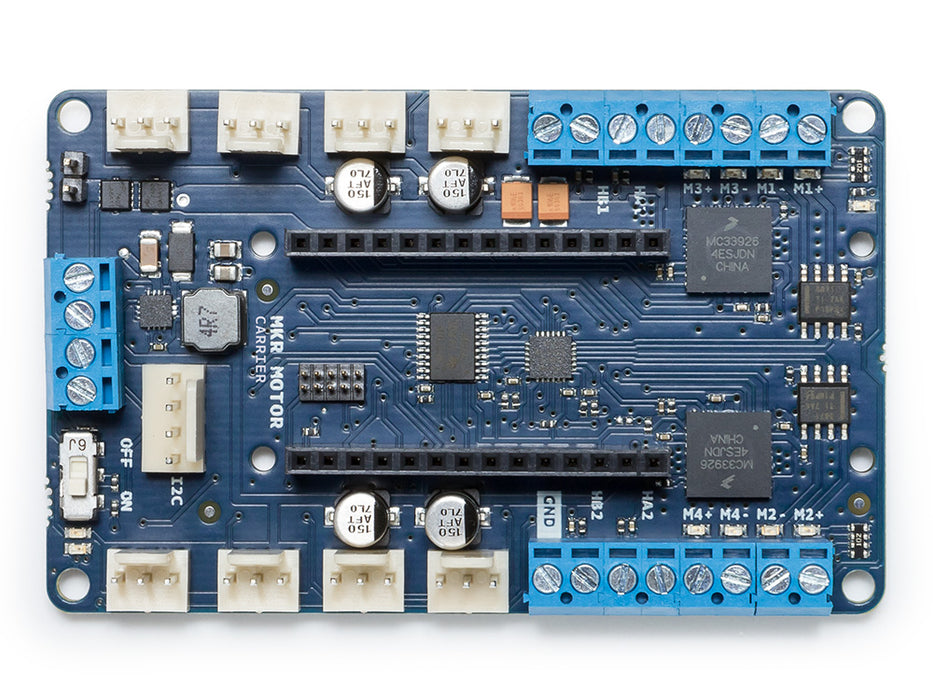
The MKR Motor Carrier is an MKR add-on board designed to control servo, DC, and stepper motors. The Carrier can also be used to connect other actuators and sensors via a series of 3-pin male headers.
The summary of features is shown below:
- Compatible with all the boards in the MKR family
- Four servo motor outputs
- Four DC motor outputs (two high performance + two standard performance)
- Sensing of current feedback for the high-performance motors
- Two inputs for encoder sensors
- Four inputs for analog sensors (3-pin compatible)
- Possibility to read the status of the batteries
- ON-OFF switch with Power ON LED
- LiPo battery connector (2S or 3S compatible) and power terminal block for alternative power source
- LEDs to visually indicate the direction of the rotation of the DC motors
- On-board processor for automated control of some of the outputs
- I2C connector as a 4-pin male header
Tech specs
|
Microcontroller |
ATSAMD11 ( Arm Cortex-M0+ processor) |
|
Max current (MC33926) |
5 Amps Peak, RMS current depending on the degree of heat sink provided |
|
Max current (DRV8871) |
3 Amps peak, current limited by current sense resistor. |
|
Rated voltage |
6.5 to 11.1V |
|
Reverse current protection |
Yes |
|
Over Temperature shutdown protection (for DC motor drivers) |
Yes |
|
Clock speed |
48 Mhz |
|
On board voltage regulator |
5V |
|
Interface |
Terminal block and 3 pin/4 pin header connector |
|
Compatibility |
MKR Family |
The MKR Motor Carrier features two MC33926 motor drivers for high-performance DC motor control with direct connection to the MKR1000, current feedback, and capacity for up to 5 Amps (peak). In addition, there are two DRV8871 drivers that are controlled from a SAMD11 microcontroller that communicates with the MKR1000 via I2C (SPI optional). The SAMD11 is also used to control the servos, read the encoders, and read the battery voltage. There is an interrupt line connecting the SAMD11 (on PA27) and the MKR board.
Note that for extended use or high-current motors, an extra heatsink (and eventually a fan) might be required for the drivers.
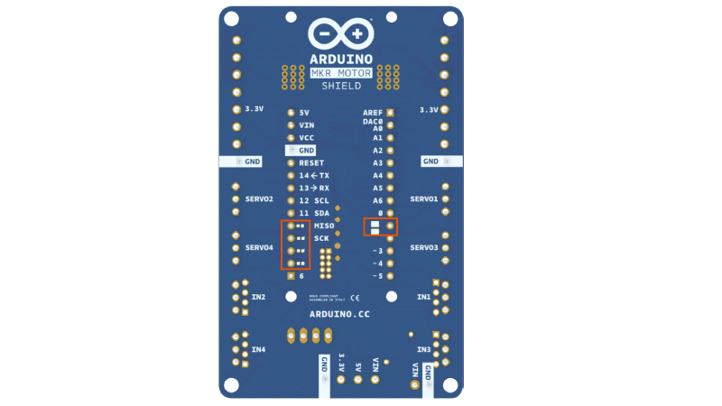
When plugging the MKR1000 and the Motor Carrier, some of the pins will stop being available for you to use in your code, as they will be needed to control some of the features of the Carrier. For example, the current feedback from the two MC33926 drivers is connected directly to some of the analog pins on the MKR1000. The following list explains which pins of the MKR1000 are used to control the Carrier:
- Analog pin A3 for current feedback from Motor3
- Analog pin A4 for current feedback from Motor4
- Digital pin D2 for IN2 signal for Motor3
- Digital pin D3 for IN1 signal for Motor3
- Digital pin D4 for IN2 signal for Motor4
- Digital pin D5 for IN1 signal for Motor4
- Digital pin D6 for Interrupt signal from the SAMD11 to the MKR1000
- Digital pin D11 for the SDA signal (I2C)
- Digital pin D12 for the SCL signal (I2C)
Also, some pins can optionally be connected via a soldering jumper or a 0 Ohm resistor. These pins are:
- Digital pin D1 for the SF signal from the MC33926 drivers (optional)
- Digital pin D7 for the SPI SS signal (optional)
- Digital pin D8 for the SPI MOSI signal (optional)
- Digital pin D9 for the SPI SCK signal (optional)
- Digital pin D10 for the SPI MISO signal (optional)
Libraries
MKR Motor carrier library
Conformities
Resources for Safety and Products
Manufacturer Information
The production information includes the address and related details of the product manufacturer.
Arduino S.r.l.
Via Andrea Appiani, 25
Monza, MB, IT, 20900
https://www.arduino.cc/
Responsible Person in the EU
An EU-based economic operator who ensures the product's compliance with the required regulations.
Arduino S.r.l.
Via Andrea Appiani, 25
Monza, MB, IT, 20900
Phone: +39 0113157477
Email: support@arduino.cc
Documentation
OSH: Schematics
The Arduino MKR Motor carrier is open-source hardware! You can build your own board using the following files:
EAGLE FILES IN .ZIP SCHEMATICS IN .PDFLearn more
Get Inspired
A Big Ben chiming clock using an Arduino Nano, a DS1302 RTC, a DFplayer Mini showing the time on a Nokia 5110 lcd with nightly cuckoo sounds
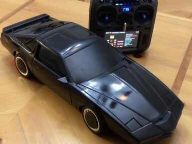
KITT (Knight Industries Two Thousand) was a fictional car based on a 1982 Pontiac Trans Am in the Knight Rider television series. KITT featured an artificial intelligence, voiced by the legendary William Daniels, and some iconic styling. Savall21 built a replica RC KITT and used Arduino boards to add sound and light effects that he can trigger with the RC transmitter. This is a custom RC car created by Savall21 using a Tamiya TT-02 kit and a resin 3D-printed body shell. The controller/transmitter is a Jumper T18, which has a customizable touchscreen interface. Savall21 programmed his own widget for that touchscreen. It mimics the fictional KITT control panel and lets the user select different sound effects and activate the iconic headlights. The T18 sends commands to an FrSky XR8 radio receiver located in the car. The FrSky receiver communicates with two Arduino Nano Every boards via the S.Port. The first Arduino controls the sound effects, which play through a DFPlayer Mini MP3 player module. The FrSky receiver simply sends a numerical code to the Arduino, which then activates the corresponding audio clip. The second Arduino drives a strip of WS2812B individually addressable RGB LEDs for the headlights and taillights. The user can control the headlights directly, while the taillights automatically come on any time the throttle is below 50%. For fans of Knight Rider and RC vehicles, this is the ultimate project. The car looks fantastic and the Arduino effects add polish to the build.


