


Overview
Portenta Breakout board is designed to help hardware engineers and makers to prototype and help test devices connections and capacity within the Portenta family boards (e.g. the Portenta H7).
It makes all high-density connectors’ signals individually accessible, making it quick and easy to connect and test external hardware components and devices as normally needed during development in the lab.
Target areas
Prototyping
Application examples
This product is designed to work alongside the Portenta family. Please check the Getting Started guide of your Portenta board.
Product Development: The Portenta Breakout board reduces development time for industrial grade solution automation based on the Portenta line.
Technical Education: The Portenta Breakout board can act as the first point of entry for technician education in industrial grade control and embedded systems.
Features
- Power ON Button
- Boot mode DIP switch
- Connectors
- USBA
- RJ45 up to 1Gb/s
- Micro SD card
- MIPI 20T JTAG with trace capability - Power
- CR2032 RTC Lithium Battery backup
- External power terminal block - I/O
- Break out all Portenta High Density connector signals
- Male/female HD connectors allow interposing breakout between Portenta and shield to debug signals - Compatibility
- Standard Portenta High Density connector pinout - Safety information
- Class A
Tech specs
| USB port | USBA |
| Ethernet | RJ45 up to 1Gb/s (Supported on Portenta X8 only) |
| Memory slot | Micro SD card |
| Debug | MIPI 20T JTAG with trace capability |
| Connectors | HD male/female |
| RTC power battery | CR2032 |
| Length | 164 mm |
| Width | 72 mm |
| Weight | 0,069 Kg |
Conformities
Resources for Safety and Products
Manufacturer Information
The production information includes the address and related details of the product manufacturer.
Arduino S.r.l.
Via Andrea Appiani, 25
Monza, MB, IT, 20900
https://www.arduino.cc/
Responsible Person in the EU
An EU-based economic operator who ensures the product's compliance with the required regulations.
Arduino S.r.l.
Via Andrea Appiani, 25
Monza, MB, IT, 20900
Phone: +39 0113157477
Email: support@arduino.cc
Documentation
Study how the Portenta Breakout Carrier works using following files:
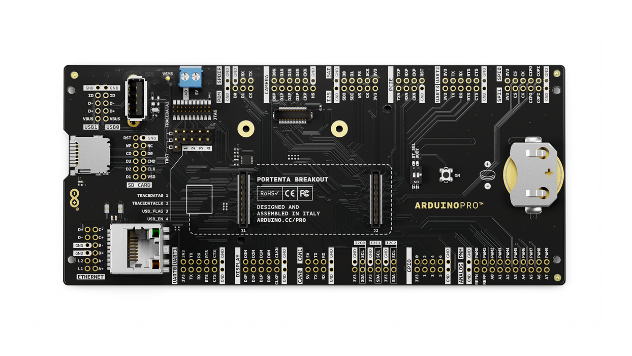
Pinout Diagram
Learn more about the portenta's pinout by reading the pinout documentation.
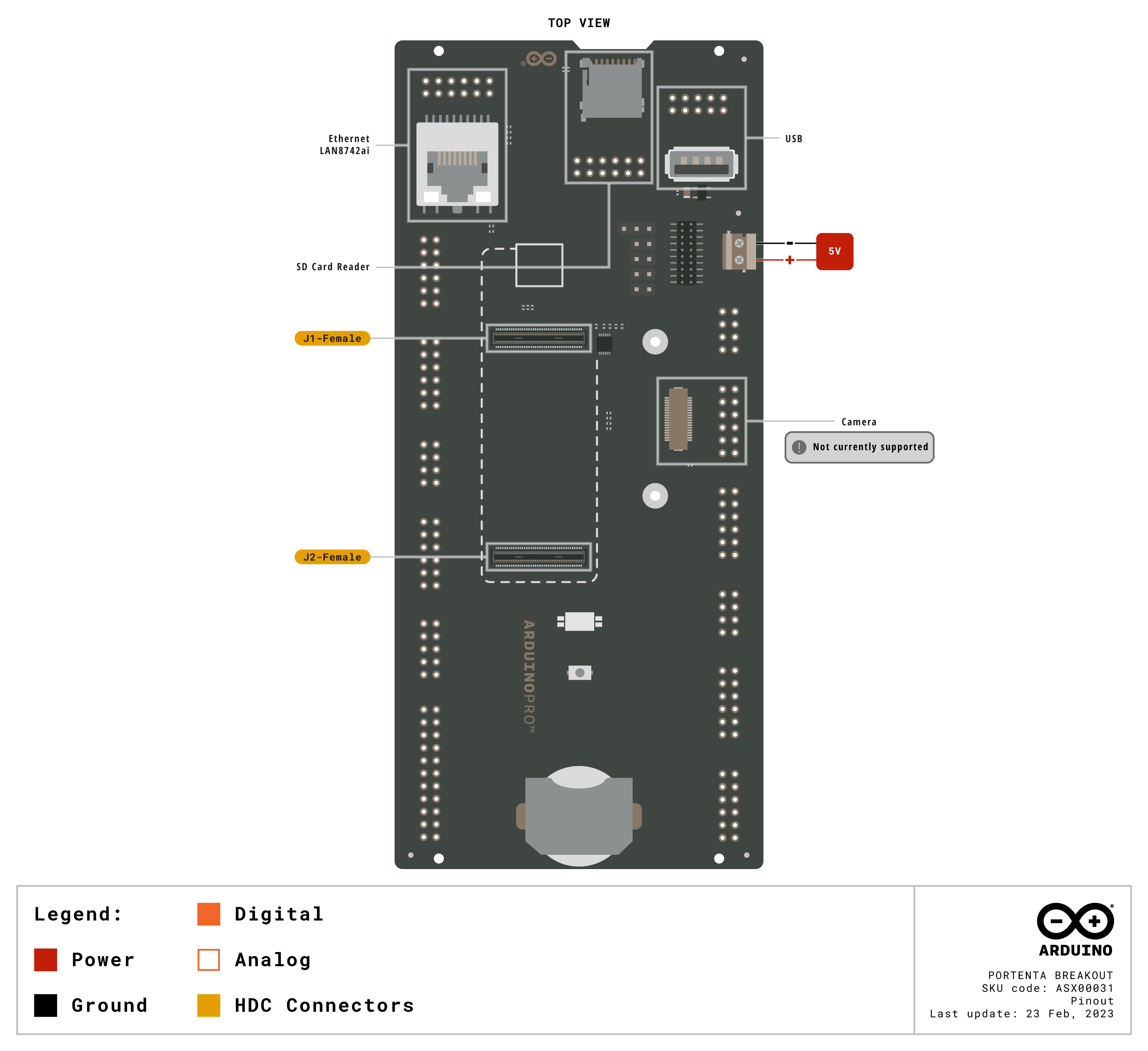
Download the full pinout diagram as PDF here.
Interactive Board Viewer
Learn more
Get Inspired
Arduino based bicycle movement sensor and GPS tracker.
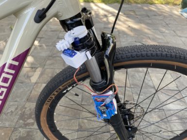
… magnetic reed switch, but building the game himself in Unity. He had to construct and animate models for himself, the bike, and the scenery. After adding an AI and ranking system to the game, he was able to successfully race within the virtual environment on a real bike. Responsive LED system Motivated by the desire for a more advanced lighting system while on her nighttime bike rides, Natasha (TechnoChic) decided to affix strips of NeoPixel LEDs all over her bike that could react to music in real-time. The LEDs are controlled by an Arduino Nano 33 IoT that is, in turn, connected to her boombox via a 3.5mm audio jack for reading the audio signal. Two additional Nano 33 IoT boards were used for the wheels, along with more NeoPixels and batteries for each. GPS tracker Bicycle theft has been rapidly increasing over the last couple of years, which is why being able to recover a stolen bike has become vital. Johan’s bike tracker project contains an Arduino MKR GSM 1400 which reads motion data from an IMU and uses it to determine if the bike has moved when it is not supposed to. Once movement is detected, the board reads GPS data from a MKR GPS Shield and sends it over an LTE data connection in real-time so that the bike can be found. Integrated safety features The majority of mountain bikes lack useful safety features such as integrated lights, turn signals, and speed tracking, which is why Collin Wentzien embarked on his “(not so) electric bike” project. He built a series of features, including automatic brake/turn lights, a headlight, and an electronic horn with the goal of improving safety. Furthermore, his bike also got a bike computer upgrade which contains an Arduino Mega, GPS module, and dual screens for displaying relevant telemetry data. Speedometer display After losing the display unit for her bike computer, Element14 Presents host Katie wanted to replace it with a DIY version that tracked the current speed


