


Arduino MKR Connector Carrier (Grove compatible)
Want to connect several Seeed Studio Grove modules to your Arduino board? The Arduino MKR CONNECTOR CARRIER is the perfect companion for Arduino MKR boards and a Grove ecosystem.
Overview
Do you have several components to connect to your project and would rather use connectors instead of soldering? The Arduino MKR CONNECTOR CARRIER provides Seeed Studio's Grove connectors to your MKR board.
The MKR CONNECTOR CARRIER shield is an essential tool for rapidly prototyping activity. It allows you to connect easily and quickly sensors with Grove connectors. This shield can allow you to build applications with different IoT connectivities by simply changing the MKR board and with almost no changes to the code.
Notice: In some Boards, there is an issue with the bottom silk being mirrored
Tech specs
| Interface | 14 Grove Connectors | |
| Analog Inputs | 5 V | |
| A0,A1,A2,A3,A4 single grove Analog input (detailed info) | ||
| A5, A6 double grove Analog input (detailed info) | ||
| Digital Input/Output | 5 V | |
| D0,D1,D2,D3,D4 single grove I/O (detailed info) | ||
| D5,D6 double grove I/O (detailed info) | ||
| Other Connectors | One 5V I2C, One 5V UART | |
| input Voltage (screw terminal block) | 7V - 16V (Buck Datasheet) | |
| Circuit Operating Voltage | 3.3V | |
| Compatibility | MKR |
Conformities
Resources for Safety and Products
Manufacturer Information
The production information includes the address and related details of the product manufacturer.
Arduino S.r.l.
Via Andrea Appiani, 25
Monza, MB, IT, 20900
https://www.arduino.cc/
Responsible Person in the EU
An EU-based economic operator who ensures the product's compliance with the required regulations.
Arduino S.r.l.
Via Andrea Appiani, 25
Monza, MB, IT, 20900
Phone: +39 0113157477
Email: support@arduino.cc
Documentation
OSH: Schematics
The Arduino MKR Connector Carrier is open-source hardware! You can build your own board using the following files:
EAGLE FILES IN .ZIP SCHEMATICS IN .PDFLearn more
Get Inspired

Another Slot Car Lap Counter, but if I did it anyone can do!
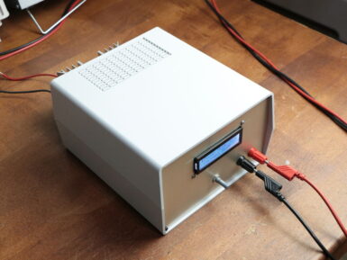
If you need a device which draws a certain amount of current and power for testing, then GreatScott! has just the solution. His project uses an Arduino Nano, along with a separate IC and a voltage divider, to measure both current and voltage input from the power source. It then employs this data to properly adjust a MOSFET, dissipating the correct amount of voltage and power as required. Interface is handled via a rotary encoder and a 16x2 I2C LCD display, and the electronics are housed in a solid-looking enclosure. As seen in the video below, the adjustable constant load features an impressively large heat sink, needed to take care of the 30V and 20A that the setup is capable of drawing.


