


Overview
The Arduino 4 Relays Shield is a solution for driving high power loads that cannot be controlled by Arduino's digital IOs, due to the current and voltage limits of the controller. The Shield features four relays, each relay provides 2 pole changeover contacts (NO and NC); in order to increase the current limit of each output the 2 changeover contacts have been put in parallel. Four LEDs indicate the on/off state of each relay.
Getting Started
You can find in the Getting Started section all the information you need to configure your board, use the Arduino Software (IDE), and start tinker with coding and electronics..
Need Help?
- On the Software on the Arduino Forum
- On Projects on the Arduino Forum
- On the Product itself through our Customer Support
Tech specs
Features
| Thinker Kit interface | 2x TWI, 2x OUT, 2x IN |
| Interfaces with Arduino Board | DIO |
| Relays | 4 (60W) |
General
| Operating Voltage | 5 V |
| Current needs | 140 mA (with all releays on, about 35 mA each) |
| PCB Size | 53 x 68.5 mm |
| Weight | 0.044 Kg |
| Product Code | A000110 |
Conformities
Resources for Safety and Products
Manufacturer Information
The production information includes the address and related details of the product manufacturer.
Arduino S.r.l.
Via Andrea Appiani, 25
Monza, MB, IT, 20900
https://www.arduino.cc/
Responsible Person in the EU
An EU-based economic operator who ensures the product's compliance with the required regulations.
Arduino S.r.l.
Via Andrea Appiani, 25
Monza, MB, IT, 20900
Phone: +39 0113157477
Email: support@arduino.cc
Documentation
OSH: Schematics
The Arduino 4 Relays Shield is open-source hardware! You can build your own board using the following files:
EAGLE FILES IN .ZIP SCHEMATICS IN .PDF
Description
|
Operating Voltage |
5V |
|
Coil current consumption |
140 mA (with all releays on, about 35 mA each) |
|
Single pole chargeover contact maximum current |
@ 30 V DC 2A |
|
Maximum load voltage |
48 V |
|
Maximum switching capacity |
60 W |
Power
The shield doesn't need external power: it will be provided by the base board, through the 5V and 3.3V pins of the Arduino board used as base.
Input and Output
The relays are controlled by the following Arduino board pins: Relay 1 = Arduino pin 4 Relay 2 = Arduino pin 7 Relay 3 = Arduino pin 8 Relay 4 = Arduino pin 12 The shield features several TinkerKit input/output and communication interfaces. Connecting TinkerKit modules can simplify the creation of a project or a prototype. The on-board connectors are :
- 2 TinkerKit Inputs: IN2 and IN3 (in white), these connectors are routed to the Arduino A2 and A3 analog input pins.
- 2 TinkerKit Outputs: OUT5 and OUT6 (in orange), these connectors are routed to the Arduino PWM outputs on pins 5 and 6.
- 2 TinkerKit TWI: these connectors (4-pin in white) are routed on the Arduino TWI interface. Both connect to the same TWI interface to allow you to create a chain of TWI devices.
Physical Characteristics
The maximum length and width of the 4 Relays Shield PCB are 2.7 and 2.1 inches respectively. Four screw holes allow the Shield to be attached to a surface or case. Note that the distance between digital pins 7 and 8 is 160 mil (0.16"), not an even multiple of the 100 mil spacing of the other pins.
Compatible Boards
The shield is compatible with all the Arduino boards, 5V and also 3.3V standards.
Learn more
Get Inspired
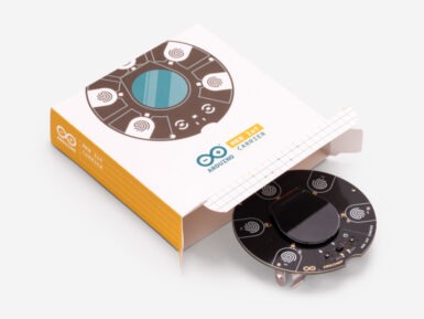
By popular demand, we are pleased to announce that it’s now possible to buy the Arduino MKR IoT Carrier. Originally forming a key part of the Arduino Oplá IoT Kit, we’ve responded to our community to make the carrier available on its own, thus enabling you to benefit from having a bunch of sensors, actuators, and a display all featured on the one board — making it quicker and easier to take your IoT projects to the next level. Featuring a large set of built-in sensors and actuators as well as a useful color display, the carrier lets you focus on prototyping your IoT ideas right away by saving on the hassle of wiring and soldering these components. The carrier can become a WiFi, LoRa, NB-IoT or GSM-compatible device by seamlessly connecting to any MKR family board. Building a user interface for these boards is easy with the embedded color OLED screen, five capacitive touch buttons, and the five RGB LEDs. The integrated sensors (temperature, humidity, pressure, RGBC light, gesture and proximity) allow you to map the environment around the carrier, and should you need to capture any other data there are over 100 additional Grove sensors that can easily be connected directly to the carrier. Here’s are quick demo of the carrier's capabilities! (Special shout out to Mirko Pacioni and Filo Connesso for creating this demo.) Capture and store all the data locally on an SD card, or connect your MKR family board to the IoT Cloud for real-time data captured, storage, and visualization. The MKR IoT Carrier features: Round OLED displayFive RGB LEDsFive capacitive touch buttonsOn-board sensors (temperature, humidity, pressure, RGBC light, gesture and proximity)BuzzerIMU (Three-axis accelerometer sensor and three-axis gyroscope sensor)Two 24V relaysMicroSD card holder (SD card not included)Plug-and-play Grove connectors for external sensors — two analog and one digital (I2C)18650 Li-ion rechargeable battery holder (battery not


