2MP GC2145 Color DVP Camera Module for Arduino GIGA R1 WiFi Board
Sold outCost effective, low power consumption, simple interface, compatibility with Arduino libraries, suitable for battery-powered and energy-efficient applications.
Overview
This camera is based on GC2415 Color rolling shutter image sensor. The GC2145 incorporates a 1616V x 1232H active pixel
array, on-chip 10-bit ADC, and image signal processor.
The 2MP GC2145 camera module is equipped with a 80°(DFOV) stock Lens. It supports RGB output format. The standrad operating temperature is between -20~70℃, with the stable Image temp. between 0~50℃.
It is fully compatible with Arduino GIGA R1 WiFi board, a professional-grade microcontroller development board recently launched by Arduino. Seamlessly integrates with our camera module, unlocking versatile image capture and processing capabilities. Harness the power of Arduino GIGA R1 WiFi and gain a competitive edge in your projects.
Features:
- Cost-Effective: Affordable solution for implementing visual capabilities in cost-sensitive projects.
- Compact Size: Compact form factor enables integration into space-constrained applications.
- Simplify Embedded Vision for All: Easy to set up and operate. Making it possible to add machine vision to your GIGA R1 board without much effort at all.
- Higher Resolution: Captures images with high resolution and detail, allowing for precise visual analysis.
- Low Power Consumption: Efficient power usage, making it suitable for battery-powered and energy-efficient applications.
Tech specs
| Image Sensor | GC2145 |
| Resolution | 2MP |
| Optical Size | 1/5'' |
| Number of effective pixels | 1616(H) × 1232(V) |
| Pixel Size | 1.75μm × 1.75μm |
| Support Platform | Arduino GIGA R1 WiFi Board |
| Shutter Type | Rolling Shutter |
| Color Filter Array | Quad-Bayer RGB |
| Frame Rate | 640x480@17fps, 320x240@27fps, 160x120@52fps |
| Output Format | RAW10 |
| F.NO | 2.2±5% |
| Focus Type | Fixed Focus |
| Focal Length | 2.2mm |
| Field of View(FOV) | 80°(D) |
| Power Supply | AVDD: 2.6V to 3.0V; DOVDD: 1.7V to 3.0V; DVDD: 1.8V |
| Operating Temperature | -20~70℃ |
| Camera Board Size | 30.5mm x 30.5mm |
Documentation
Get Inspired

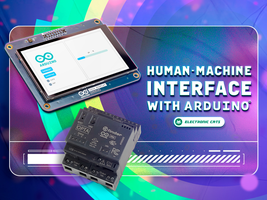
Learn how to build a complete HMI with Arduino that will allow you to interact with your projects in an intuitive and visual way.

OPC Unified Architecture – OPC UA in short – is a cross-platform, open-source machine-to-machine communication protocol for industrial automation. It was developed by the Open Platform Communications (OPC) Foundation and is defined in detail in the IEC 62541 standard. With the release of the Arduino_OPC_UA library we enable users to convert any product from our Arduino Opta range into an OPC UA-enabled device. Step-by-step guide to setting up OPC UA on Arduino Opta It’s as simple as uploading a single sketch onto your Opta and connecting it to an Ethernet network. Once uploaded, the OPC UA firmware exposes the Arduino Opta’s analog and digital inputs, the user button and LED (only Arduino Opta WiFi), as well as its relay outputs as properties that can be read from or written to using OPC UA. OPC UA communication is performed using OPC UA binary encoding via TCP sockets. Arduino_OPC_UA is a port of the Fraunhofer open62541 library implementing IEC 62541 in highly portable C99 for both Windows and Linux targets. One serious challenge during the porting of open62541 was to decide on sensible tradeoffs concerning RAM consumption, as using OPC UAs full namespace zero (NS0) requires up to 8 MB of RAM while the STM32H747 powering the Arduino Opta has a total of 1 MB of SRAM to offer – some of which already allocated by the the Arduino framework for the Arduino Opta. Expand functionality with Arduino Opta Modules and OPC UA integration Additionally, Arduino_OPC_UA supports the automatic discovery, configuration and exposure as OPC UA objects of the recently released Arduino Opta expansion modules. Currently three different expansion modules exist: Arduino Opta Analog Expansion (A0602), Arduino Opta Digital Expansion with electro-mechanical relay outputs (D1608E), and with solid-state relay outputs (DS1608S). During system start-up, the Arduino Opta’s expansion bus is queried for connected expansion modules and automatically configures them and


