Overview
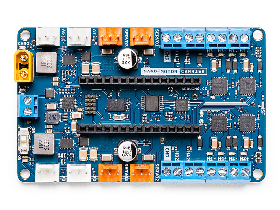
Nano Motor Carrier is the perfect add-on for the Nano 33 IoT board as it works to extend and power up its functionality.
Designed to facilitate motor control, Nano Motor Carrier takes care of the electronics required to control motors, allowing students to focus on prototyping and building their projects. It can also be used to connect other actuators and sensors via a series of 3-pin male headers. The board features are: on board 9 axis accelerometer, gyroscope and magnetometer. It includes a battery charger for single cell Li-ion batteries and it contains 2 ports for quadrature encoder counting.
To use the carrier, simply connect it to a Nano 33 board and attach the motors you need for your project. Once connected, attach the USB cable to the Nano 33 IoT. Download Arduino Motor Carrier library from the library manager and you’re all set up to start programming and controlling your motors using the motor drivers.
When working with motors, you need an external power source to feed the motor drivers and power the motors. You can do this by connecting a 1 cell Li-Ion battery to the battery connector or by using an external power source.
Tech specs
|
Microcontroller |
ATSAMD11 ( Arm Cortex-M0+ @48 Mhz) |
| Motor Drivers (x4) | MP6522 |
| Max Input voltage (power terminals) | 4V (1S Li-Ion Battery) |
| Max output current per motor driver | 500 mA |
| Motor driver output voltage | 12V |
| Over Temperature shutdown protection (for DC motor drivers) | Yes |
| Battery charging | Yes |
| Max battery charging current | 500mA (configurable) |
| Power terminals (connectors) | XT-30 and 2POS terminal block |
| Servo connector | 4 terminals |
| Encoder inputs | 2 ports |
| DC motor control | 4 ports |
| 3V digital/analog sensor input/output | 4 ports |
| IMU | BNO055 9axis Acc/Gyr/Mag |
Resources for Safety and Products
Manufacturer Information
The production information includes the address and related details of the product manufacturer.
Arduino S.r.l.
Via Andrea Appiani, 25
Monza, MB, IT, 20900
https://www.arduino.cc/
Responsible Person in the EU
An EU-based economic operator who ensures the product's compliance with the required regulations.
Arduino S.r.l.
Via Andrea Appiani, 25
Monza, MB, IT, 20900
Phone: +39 0113157477
Email: support@arduino.cc
Documentation
OSH: Schematics
Arduino Nano Motor Carrier is open-source hardware! You can build your own board using the following files:
Learn more
Get Inspired

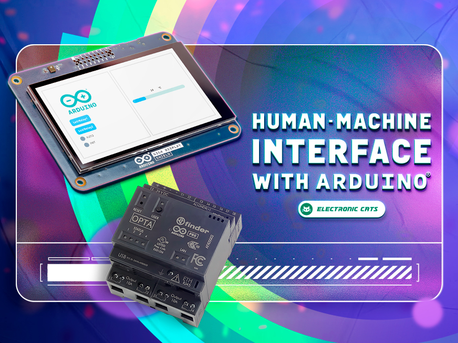
Learn how to build a complete HMI with Arduino that will allow you to interact with your projects in an intuitive and visual way.

OPC Unified Architecture – OPC UA in short – is a cross-platform, open-source machine-to-machine communication protocol for industrial automation. It was developed by the Open Platform Communications (OPC) Foundation and is defined in detail in the IEC 62541 standard. With the release of the Arduino_OPC_UA library we enable users to convert any product from our Arduino Opta range into an OPC UA-enabled device. Step-by-step guide to setting up OPC UA on Arduino Opta It’s as simple as uploading a single sketch onto your Opta and connecting it to an Ethernet network. Once uploaded, the OPC UA firmware exposes the Arduino Opta’s analog and digital inputs, the user button and LED (only Arduino Opta WiFi), as well as its relay outputs as properties that can be read from or written to using OPC UA. OPC UA communication is performed using OPC UA binary encoding via TCP sockets. Arduino_OPC_UA is a port of the Fraunhofer open62541 library implementing IEC 62541 in highly portable C99 for both Windows and Linux targets. One serious challenge during the porting of open62541 was to decide on sensible tradeoffs concerning RAM consumption, as using OPC UAs full namespace zero (NS0) requires up to 8 MB of RAM while the STM32H747 powering the Arduino Opta has a total of 1 MB of SRAM to offer – some of which already allocated by the the Arduino framework for the Arduino Opta. Expand functionality with Arduino Opta Modules and OPC UA integration Additionally, Arduino_OPC_UA supports the automatic discovery, configuration and exposure as OPC UA objects of the recently released Arduino Opta expansion modules. Currently three different expansion modules exist: Arduino Opta Analog Expansion (A0602), Arduino Opta Digital Expansion with electro-mechanical relay outputs (D1608E), and with solid-state relay outputs (DS1608S). During system start-up, the Arduino Opta’s expansion bus is queried for connected expansion modules and automatically configures them and


