


Portenta Vision Shield - Ethernet
Professional computer vision, directional audio detection, Ethernet, and JTAG for Arduino Portenta.
The Portenta Vision Shield is also available with LoRa® connectivity. Check it out here!
Overview
The Portenta Vision Shield brings industry-rated features to your Portenta. This hardware add-on will let you run embedded computer vision applications, connect wirelessly or via Ethernet to the Arduino Cloud or your own infrastructure, and activate your system upon the detection of sound events.
The shield comes with:
- a 320x320 pixels camera sensor: use one of the cores in Portenta to run image recognition algorithms using the OpenMV for Arduino editor
- a 100 Mbps Ethernet connector: get your Portenta H7 connected to the wired Internet
- two on-board microphones for directional sound detection: capture and analyze sound in real time
- JTAG connector: perform low-level debugging of your Portenta board or special firmware updates using an external programmer
- SD-Card connector: store your captured data in the card, or read configuration files
The Vision Shield Ethernet has been designed to work with the Portenta H7. The Portenta boards feature multicore 32-bit ARM® Cortex® processors running at hundreds of megahertz, with megabytes of program memory and RAM. Portenta boards come with WiFi and Bluetooth®. Purchase this Shield together with the Portenta H7 for full performance.
Embedded Computer Vision Made Easy
Arduino has teamed up with OpenMV to offer you a free license to the OpenMV IDE, an e
asy way into computer vision using MicroPython as a programming paradigm. Download the OpenMV for Arduino Editor from our professional tutorials site and browse through the examples we have prepared for you inside the OpenMV IDE. Companies across the whole world are already building their commercial products based on this simple-yet-powerful approach to detect, filter, and classify images, QR codes, and others.

QR code detection example
Blob analysis example
Debugging With Professional Tools
Connect your Portenta H7 to a professional debugger through the JTAG connector. Use professional software tools like the ones from Lauterbach or Segger on top of your board to debug your code step by step. The Vision Shield exposes the required pins for you to plug in your external JTAG.
Getting Started
The Portenta tutorials section at the Arduino Docs website contains all the information you need to configure the Portenta H7, as well as the Vision Shield, and the OpenMV editor for computer vision applications.
Need Help?
Check the Arduino Forum for questions about the Arduino Language, or how to make your own Projects with Arduino. Need any help with your board please get in touch with the official Arduino User Support as explained in our Contact Us page.
Warranty
You can find here your board warranty information.
Tech specs
The Arduino Vision Shield is an active add-on to the Portenta family of boards.
| Camera | Himax HM-01B0 camera module (manufacturer site) |
| Resolution | 320 x 320 active pixel resolution with support for QVGA |
| Image sensor | High sensitivity 3.6μ BrightSense™ pixel technology |
| Microphone | 2 x MP34DT05 (datasheet) |
| Length | 66 mm |
| Width | 25 mm |
| Weight | 11 gr |
Conformities
Resources for Safety and Products
Manufacturer Information
The production information includes the address and related details of the product manufacturer.
Arduino S.r.l.
Via Andrea Appiani, 25
Monza, MB, IT, 20900
https://www.arduino.cc/
Responsible Person in the EU
An EU-based economic operator who ensures the product's compliance with the required regulations.
Arduino S.r.l.
Via Andrea Appiani, 25
Monza, MB, IT, 20900
Phone: +39 0113157477
Email: support@arduino.cc
Documentation
Learn more about the Portenta Vision Shield using the following files:
SCHEMATICS IN .PDF DATASHEET IN .PDF
Pinout Diagram
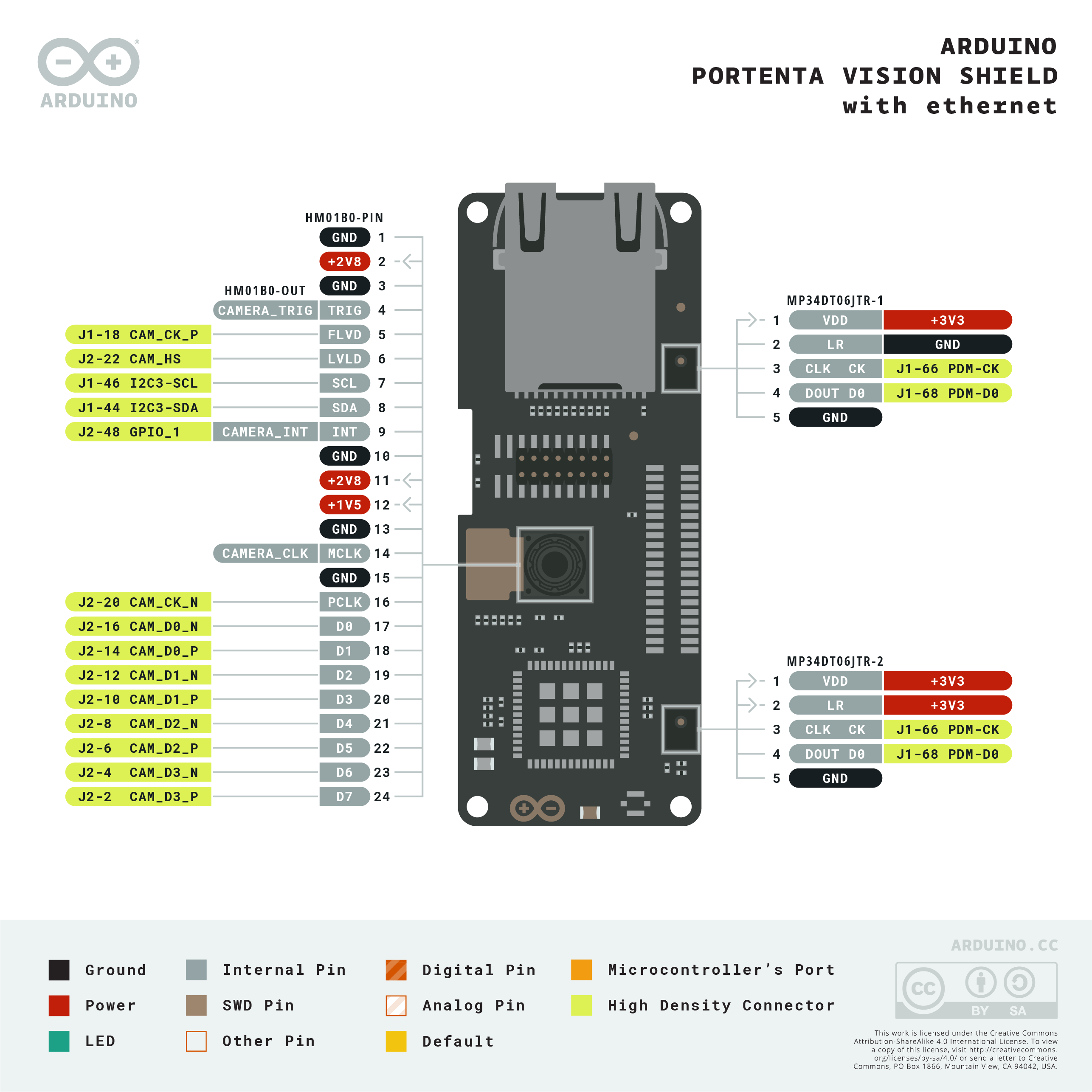
Download the full pinout diagram as PDF here.
Learn more
Get Inspired
Using the Garmin LIDARLite v3HP, Arduino MKR WIFI 1010 and Pushsafer to detect an intruder and send a push notification to a smartphone.
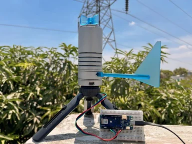
Being able to monitor the weather in real-time is great for education, research, or simply to analyze how the local climate changes over time. This project by Hackster.io user Pradeep explores how he was able to design a simple station outdoors that could communicate with a cloud-based platform for aggregating the sensed data. The board Pradeep selected is the Arduino MKR WiFi 1010 owing to its low-power SAM D21 microcontroller and Wi-Fi/BLE connectivity for easy, wireless communication. After configured, he connected a DFRobot Lark Weather Station, which contains sensors for measuring wind speed/direction, temperature, humidity, and barometric pressure — all in a compact device. Every second, the MKR WiFi 1010’s sketch polls the sensors for new data over I2C before printing it to USB. The cloud integration aspect was achieved by leveraging Qubitro’s platform to collect and store the data for later visualization and analysis. To set it up, Pradeep created a new device connection and copied the resulting MQTT endpoint/token into his sketch. Then once new data became ready, it got serialized into a JSON payload and sent to the topic where a variety of widgets could then show dials and charts of each weather-related metric. To read more about this DIY weather station, you can visit Pradeep’s project write-up here.


