


Overview
The Arduino 4 Relays Shield is a solution for driving high power loads that cannot be controlled by Arduino's digital IOs, due to the current and voltage limits of the controller. The Shield features four relays, each relay provides 2 pole changeover contacts (NO and NC); in order to increase the current limit of each output the 2 changeover contacts have been put in parallel. Four LEDs indicate the on/off state of each relay.
Getting Started
You can find in the Getting Started section all the information you need to configure your board, use the Arduino Software (IDE), and start tinker with coding and electronics..
Need Help?
- On the Software on the Arduino Forum
- On Projects on the Arduino Forum
- On the Product itself through our Customer Support
Tech specs
Features
| Thinker Kit interface | 2x TWI, 2x OUT, 2x IN |
| Interfaces with Arduino Board | DIO |
| Relays | 4 (60W) |
General
| Operating Voltage | 5 V |
| Current needs | 140 mA (with all releays on, about 35 mA each) |
| PCB Size | 53 x 68.5 mm |
| Weight | 0.044 Kg |
| Product Code | A000110 |
Conformities
Resources for Safety and Products
Manufacturer Information
The production information includes the address and related details of the product manufacturer.
Arduino S.r.l.
Via Andrea Appiani, 25
Monza, MB, IT, 20900
https://www.arduino.cc/
Responsible Person in the EU
An EU-based economic operator who ensures the product's compliance with the required regulations.
Arduino S.r.l.
Via Andrea Appiani, 25
Monza, MB, IT, 20900
Phone: +39 0113157477
Email: support@arduino.cc
Documentation
OSH: Schematics
The Arduino 4 Relays Shield is open-source hardware! You can build your own board using the following files:
EAGLE FILES IN .ZIP SCHEMATICS IN .PDF
Description
|
Operating Voltage |
5V |
|
Coil current consumption |
140 mA (with all releays on, about 35 mA each) |
|
Single pole chargeover contact maximum current |
@ 30 V DC 2A |
|
Maximum load voltage |
48 V |
|
Maximum switching capacity |
60 W |
Power
The shield doesn't need external power: it will be provided by the base board, through the 5V and 3.3V pins of the Arduino board used as base.
Input and Output
The relays are controlled by the following Arduino board pins: Relay 1 = Arduino pin 4 Relay 2 = Arduino pin 7 Relay 3 = Arduino pin 8 Relay 4 = Arduino pin 12 The shield features several TinkerKit input/output and communication interfaces. Connecting TinkerKit modules can simplify the creation of a project or a prototype. The on-board connectors are :
- 2 TinkerKit Inputs: IN2 and IN3 (in white), these connectors are routed to the Arduino A2 and A3 analog input pins.
- 2 TinkerKit Outputs: OUT5 and OUT6 (in orange), these connectors are routed to the Arduino PWM outputs on pins 5 and 6.
- 2 TinkerKit TWI: these connectors (4-pin in white) are routed on the Arduino TWI interface. Both connect to the same TWI interface to allow you to create a chain of TWI devices.
Physical Characteristics
The maximum length and width of the 4 Relays Shield PCB are 2.7 and 2.1 inches respectively. Four screw holes allow the Shield to be attached to a surface or case. Note that the distance between digital pins 7 and 8 is 160 mil (0.16"), not an even multiple of the 100 mil spacing of the other pins.
Compatible Boards
The shield is compatible with all the Arduino boards, 5V and also 3.3V standards.
Learn more
Get Inspired
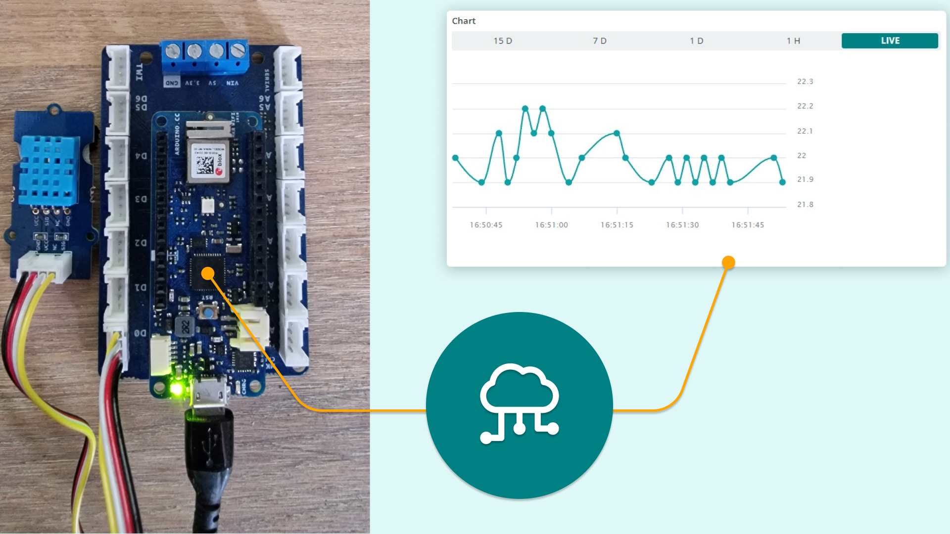
Easy data logging with grove sensors using the MKR Connector Carrier and MKR boards
If you’re looking for an ever faster, smoother, and more rewarding way to build your own IoT projects at home, the new MKR IoT Carrier Rev2 could be perfect for you. The new carrier can work with any board from the MKR family, giving you a wide choice of connectivity options to match the needs of your next IoT project. The MKR IoT Carrier Rev2 doesn't require any additional components to get started, and you can create impressive and complete hassle-free projects this way. What does the carrier include? You’ll get all the sensors and actuators you need to develop IoT projects and connect them to the internet, taking your home automation journey to the next level. Let’s take a quick look at what you can build with the MKR IoT Carrier Rev2 and any board from the MKR family. Environment monitoring stations. The new carrier comes with sensors that allow you to map and measure various things in the world around you — temperature, humidity, air quality, barometric pressure, and more. You can also track the movement of the board. For even more sensory awareness, you can connect analog or I2C grove compatible modules to the grove connectors. You can store the data you collect in the SD card or send it directly to the Arduino IoT Cloud. GUI IoT interface. Visualizing your data is incredibly important — and the Rev2 comes with its own OLED color display, allowing you to create your own navigation menus. You can also use the included LEDs and buzzer for feedback. Connect to and control external devices. The IoT is all about networks, and with the Rev2 you can control electronic devices up to 24 Volts using the two on-board relays. You can do this manually — like switching your reading lamp on or off via the Arduino IoT Cloud Remote app, or you can set the lamp to behave according to sensor data like the light levels in the room. The MKR IoT Carrier vs the MKR IoT Carrier Rev2 — what’s the difference? There are a few key differences


