


Overview
Introduction
The Education Shield is a custom-made shield designed by Arduino Education, specially tailored for educational purposes to enable quick and easy learning while building projects. The shield is meant to be used in conjuction with the CTC Program. It connects to an Arduino 101 or UNO and extend their capabilities. The shield has a collection of features that make building small projects in or outside of the classroom easy:
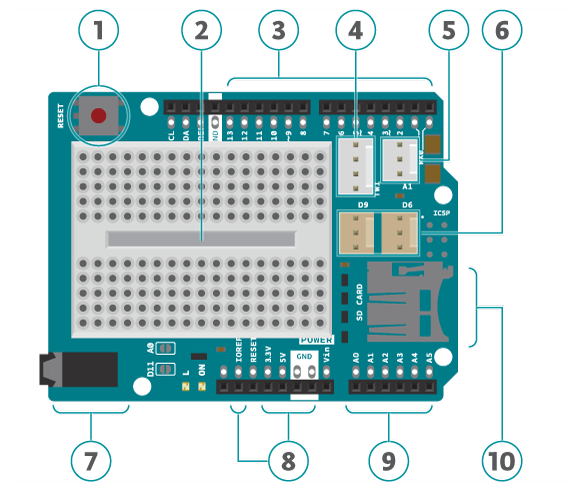
- Reset button. When this is pressed the program uploaded to the control board is restarted.
- Built in protoshield or used as a placement of breadboard.
- Digital input and output pins. Directly connected to the digital pins on the board.
- I2C connector.
- A1 3-pin header port: Analog out/in. This can also be used as a digital in/out.
- D6 and D9: digital 3-pin header ports connected to digital pin 6 and 9.
- Speaker plug:This is connected to digital pin 11.
- Ground and power pins. The voltage supply pin used in CTC is the IOREF pin. This pin outputs different voltages depending on the board (101 board: 3.3V, UNO board: 5V).
- Analog input/output pins.
- SD card reader/writer connected to digital pins 10 to 13.
Note:
- Avoid using analog A4 and A5. These have pull-up resistors connected to them and you should avoid using unless you know what you are doing.
- Do not use digital pins 4, 10, 11, 12 and 13 when using the micro SD card reader.
- Digital pins 9 to 13 cannot be used for capacitive sensors, these are connected to the SD card reader which has resistors and might therefore provide false readings.
- Digital pin 6, 9 and analog pin A1 are connected to component module ports. If the ports are used don’t use the corresponding pins.
- Digital pin 11 is connected to the audio socket. If the socket is in use don't use the pin.
Use Modules with simple connectors
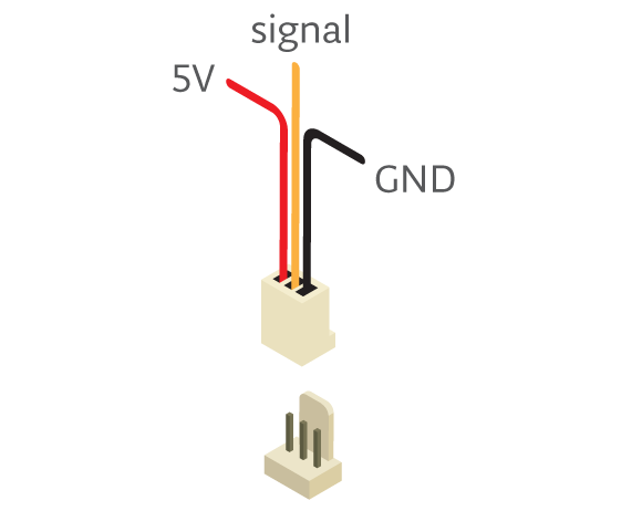
A simple 3 pin connector, that snaps in place, is used for all 3-pin modules. Here are some examples of components All these make connecting and prototyping easier through their simplified design: Push button modules, light sensor modules, and power LED modules.
If you’re trying to connect servos or other 3-pin modules, be sure about the direction of the connector so that GND is connected to GND, power to power and signal to signal. The color of a simple connector wire helps you remember it: red means power, orange or white means signal, and black means GND. Technically you can connect modules with simple connectors without 3-pin ports, as long as you plug the wires to the right pins.
Tech specs
|
Connectors |
1x I2C 4-pin connector* 1x 3-pin analog connector* 2x digital 3-pin connector* 1x pwm audiojack Plus extensions of the pins from the board. *Sullins Connector Solutions SWR25X series connector, commonly called “tinkerkit” connector” |
|
Interfaces with Arduino Board |
DIO |
|
Operating Voltage |
3.3 V (Arduino 101) or 5 V (Arduino Uno) |
|
PCB Size |
53 x 71.2 mm |
Conformities
Resources for Safety and Products
Manufacturer Information
The production information includes the address and related details of the product manufacturer.
Arduino S.r.l.
Via Andrea Appiani, 25
Monza, MB, IT, 20900
https://www.arduino.cc/
Responsible Person in the EU
An EU-based economic operator who ensures the product's compliance with the required regulations.
Arduino S.r.l.
Via Andrea Appiani, 25
Monza, MB, IT, 20900
Phone: +39 0113157477
Email: support@arduino.cc
Documentation
OSH: Schematics
The Arduino Education Shield is open-source hardware! You can build your own board using the following files:
Get Inspired
My project has a Nodemcu ESP8266 which is controlling a 7-segment display through the http server using html form.
… remote monitoring and control. 2. Embed a web server in the device Embedding a web server inside the IoT device allows you to visualize the data using a web browser. It requires the device to have network connectivity, and it is usually implemented connecting the device to a Wi-Fi access point or with the device creating its own WiFi hotspot. Although creating your own web server implementation can be done, one of the most widespread solutions is to make use of the library ESPAsyncWebServer. It allows your IoT device to serve custom HTML pages presenting the data. This is a very flexible and customizable solution, yet complex and mostly suitable for skilled users. There are plenty of insightful examples like the following ones: ESP32 Web Server - Arduino IDE | Random Nerd TutorialsArduino Project Hub - NodeMCU ESP8266 AJAX Enabled Web Server Arduino Project Hub - WiFi Robot Car / RC Car NodeMCU Web ServerESP32 Web Server: Display Sensor Readings in Gauges | Random Nerd Tutorials The scope of this solution is typically local — you need to be on the same network as the device — although with a more advanced configuration by enabling port forwarding in the router, the device could be accessed remotely from anywhere. One of the main advantages is its low latency, as the data shown in the web page comes directly from the device without any processing. On the other hand, it is a solution that requires a high programming skill level and additionally, due to the immutable nature of the firmware, every change in a dashboard requires code recompilation and firmware reflashing. Furthermore, embedding a web server or a Bluetooth stack within the device can be resource-intensive. This may limit the device's capabilities or require a more powerful microcontroller, increasing both cost and complexity. 3. Send data to an external system with plotting capabilities IoT devices can send data to external systems using different protocols, such as


