


Overview
The Arduino Motor Shield is based on the L298 (datasheet), which is a dual full-bridge driver designed to drive inductive loads such as relays, solenoids, DC and stepping motors. It lets you drive two DC motors with your Arduino board, controlling the speed and direction of each one independently. You can also measure the motor current absorption of each motor, among other features. The shield is TinkerKit compatible, which means you can quickly create projects by plugging TinkerKit modules to the board.
Getting Started
You can find in the Getting Started section all the information you need to configure your board, use the Arduino Software (IDE), and start tinker with coding and electronics.
Need Help?
- On the Software on the Arduino Forum
- On Projects on the Arduino Forum
- On the Product itself through our Customer Support
Tech specs
| Operating Voltage | 5V to 12V |
| Motor controller | L298P, Drives 2 DC motors or 1 stepper motor |
| Max current | 2A per channel or 4A max (with external power supply) |
| Current sensing | 1.65V/A |
| Free running stop and brake function |
Conformities
Resources for Safety and Products
Manufacturer Information
The production information includes the address and related details of the product manufacturer.
Arduino S.r.l.
Via Andrea Appiani, 25
Monza, MB, IT, 20900
https://www.arduino.cc/
Responsible Person in the EU
An EU-based economic operator who ensures the product's compliance with the required regulations.
Arduino S.r.l.
Via Andrea Appiani, 25
Monza, MB, IT, 20900
Phone: +39 0113157477
Email: support@arduino.cc
Documentation
OSH: Schematics
The Arduino Motor Shield is open-source hardware! You can build your own board using the following files:
EAGLE FILES IN .ZIP SCHEMATICS IN .PDF
Power
The Arduino Motor Shield must be powered only by an external power supply. Because the L298 IC mounted on the shield has two separate power connections, one for the logic and one for the motor supply driver. The required motor current often exceeds the maximum USB current rating.
External (non-USB) power can come either from an AC-to-DC adapter (wall-wart) or battery. The adapter can be connected by plugging a 2.1mm center-positive plug into the Arduino's board power jack on which the motor shield is mounted or by connecting the wires that lead the power supply to the Vin and GND screw terminals, taking care to respect the polarities.
To avoid possible damage to the Arduino board on which the shield is mounted, we reccomend using an external power supply that provides a voltage between 7 and 12V. If your motor require more than 9V we recommend that you separate the power lines of the shield and the Arduino board on which the shield is mounted. This is possible by cutting the "Vin Connect" jumper placed on the back side of the shield. The absolute limit for the Vin at the screw terminals is 18V.
The power pins are as follows:
- Vin on the screw terminal block, is the input voltage to the motor connected to the shield. An external power supply connected to this pin also provide power to the Arduino board on which is mounted. By cutting the "Vin Connect" jumper you make this a dedicated power line for the motor.
- GND Ground on the screw terminal block.
The shield can supply 2 amperes per channel, for a total of 4 amperes maximum.
Input and Output
This shield has two separate channels, called A and B, that each use 4 of the Arduino pins to drive or sense the motor. In total there are 8 pins in use on this shield. You can use each channel separately to drive two DC motors or combine them to drive one bipolar stepper motor. The shield's pins, divided by channel are shown in the table below:
| Function | pins per Ch. A | pins per Ch. B |
| Direction | D12 | D13 |
| PWM | D3 | D11 |
| Brake | D9 | D8 |
| Current Sensing | A0 | A1 |
If you don't need the Brake and the Current Sensing and you also need more pins for your application you can disable this features by cutting the respective jumpers on the back side of the shield.
The additional sockets on the shield are described as follow:
- Screw terminal to connect the motors and their power supply.
- 2 TinkerKit connectors for two Analog Inputs (in white), connected to A2 and A3.
- 2 TinkerKit connectors for two Aanlog Outputs (in orange in the middle), connected to PWM outputs on pins D5 and D6.
- 2 TinkerKit connectors for the TWI interface (in white with 4 pins), one for input and the other one for output.
Motors Connection
Brushed DC motor. You can drive two Brushed DC motors by connecting the two wires of each one in the (+) and (-) screw terminals for each channel A and B. In this way you can control its direction by setting HIGH or LOW the DIR A and DIR B pins, you can control the speed by varying the PWM A and PWM B duty cycle values. The Brake A and Brake B pins, if set HIGH, will effectively brake the DC motors rather than let them slow down by cutting the power. You can measure the current going through the DC motor by reading the SNS0 and SNS1 pins. On each channel will be a voltage proportional to the measured current, which can be read as a normal analog input, through the function analogRead() on the analog input A0 and A1. For your convenience it is calibrated to be 3.3V when the channel is delivering its maximum possible current, that is 2A.
Physical Characteristics
The maximum length and width of the Motor Shield PCB are 2.7 and 2.1 inches respectively. Four screw holes allow the board to be attached to a surface or case. Note that the distance between digital pins 7 and 8 is 160 mil (0.16"), not an even multiple of the 100 mil spacing of the other pins.
Learn more
Get Inspired
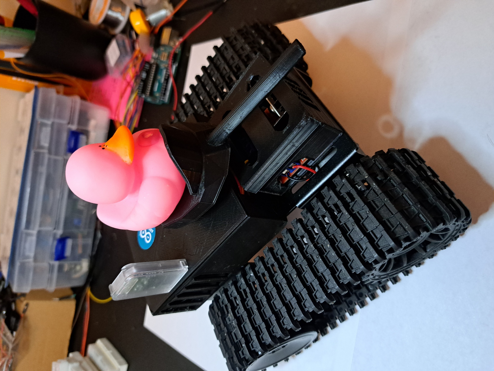
I'm excited to share the details of my BT Arduino Tank project, which incorporates some impressive 3D-printed components. While the main chassis of the tank was not 3D-printed, I utilized this technology to create two crucial parts: the enclosure for the motor driver and the compartment housing the remaining electronics. Additionally, I 3D-printed a cannon for an added touch of customization. The enclosure for the motor driver served as a protective housing, ensuring that the L298N motor driver module was securely mounted and shielded from external elements. By designing and 3D-printing this part, I could precisely fit it to the tank's specifications, providing a neat and organized arrangement of the electronics. In the same vein, the compartment for the remaining electronics, such as the Arduino Nano Every and the HC-05 Bluetooth module, was also 3D-printed. This enclosure offered a clean and organized solution for housing these components, safeguarding them while maintaining easy access for maintenance or modifications. Lastly, to enhance the tank's appearance and add a touch of personalization, I designed and 3D-printed a cannon. This custom-printed cannon perfectly complemented the overall design, making the tank even more visually appealing. By strategically incorporating 3D printing into specific parts of the project, I achieved a balance between functionality and customization. The precision and versatility of 3D printing allowed me to create tailored enclosures and a unique cannon, elevating the overall aesthetic and practicality of my BT Arduino Tank project.
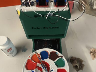
When you want to paint the walls in your bedroom that very specific shade of Misty Irish Green, all you have to do is head to your local hardware store and have them scan the corresponding card. The paint-mixing machine will then add the pigment to a white base and, a few minutes later, you have that exact color. So, shouldn’t you be able to do the same thing with acrylic paint for hobby purposes? Now you can, thanks to the “Color By Code” machine designed by Caltech students Frida Moreno and Asmat Kaur Taunque. Moreno and Taunque built Color By Code for a class project and it is, essentially, a hobby version of those hardware store paint-mixers intended for acrylic paint. As is the standard across many industries that deal with pigments, paint, and printing, this works using CMYK (cyan, magenta, yellow, key) color mixing. Here, the key is black and the machine takes an input color value for each component, then dispenses the paint in those ratios to achieve the desired hue. That all happens under the control of an Arduino Nano Every board. That operates peristaltic pumps, via L298N motor drivers, that dispense each color. Afterwards, a flushing procedure clears the lines before the next mix. The pumps fit into a 3D-printed stand, with the hoses dropping below to a waiting container. At this time, the user must set the color values through serial commands. But the team hopes to create a Bluetooth app in the future. They also plan to add a weight sensor, which would improve the machine’s accuracy.


