


Multi-function Environmental Module - CCS811+BME280
Sold outBuild up a simple environmental monitor station with this multi-function environment sensor!
Overview
Build up a simple environmental monitor station with this multi-function environment sensor! Based on the combination of CCS811+BME280 chip, this module features high accuracy, I2C interface, and fast Measurement.
The BME280 can provide temperature and humidity compensation for CCS811 to improve the whole accuracy to a certain extent. It can be used to detect temperature, humidity, barometric pressure, altitude, TVOC, and eCO2.
CCS811 air quality sensor uses AMS's unique micro-hot plate technology. Compared with conventional gas sensors, it has lower power consumption, shorter preheating time, and smaller size. The internally integrated ADC and MCU allow it to collect and process data, and return via I2C.
BME280 is an environmental sensor that combines temperature sensor, humidity sensor, and barometer in one board. It has high precision, multiple functions, small size, etc. The sensor offers ±0.5℃ temperature error and ±2%RH humidity error.
It provides very stable performance within the detection temperature range. Besides, the offset temperature coefficient is ±1.5 Pa/K, equiv. to ±12.6 cm at 1 °C temperature change.
NOTE: The chip has stretched the clock in I2C. So, it may be not compatible with some controllers, such as Raspberry Pi.
Get Inspired
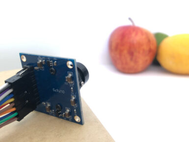
If you’re interested in embedded machine learning (TinyML) on the Arduino Nano 33 BLE Sense, you’ll have found a ton of on-board sensors — digital microphone, accelerometer, gyro, magnetometer, light, proximity, temperature, humidity and color — but realized that for vision you need to attach an external camera. In this article, we will show you how to get image data from a low-cost VGA camera module. We’ll be using the Arduino_OVD767x library to make the software side of things simpler. Hardware setup To get started, you will need: Arduino Nano 33 BLE Sense with headersOV7670 CMOS VGA Camera Module 16x female to female jumper wiresA microUSB cable to connect to your Arduino You can of course get a board without headers and solder instead, if that's your preference. The one downside to this setup is that (in module form) there are a lot of jumpers to connect. It’s not hard but you need to take care to connect the right cables at either end. You can use tape to secure the wires once things are done, lest one comes loose. You need to connect the wires as follows: Software setup First, install the Arduino IDE or register for Arduino Create tools. Once you install and open your environment, the camera library is available in the library manager. Install the Arduino IDE or register for Arduino CreateTools > Manage Libraries and search for the OV767 libraryPress the Install button Now, we will use the example sketch to test the cables are connected correctly: Examples > Arduino_OV767X > CameraCaptureRawBytesUncomment (remove the //) from line 48 to display a test pattern Compile and upload to your board Your Arduino is now outputting raw image binary over serial. To view this as an image we’ve included a special application to view the image output from the camera using Processing. Processing is a simple programming environment that was created by graduate students at MIT Media Lab to make


