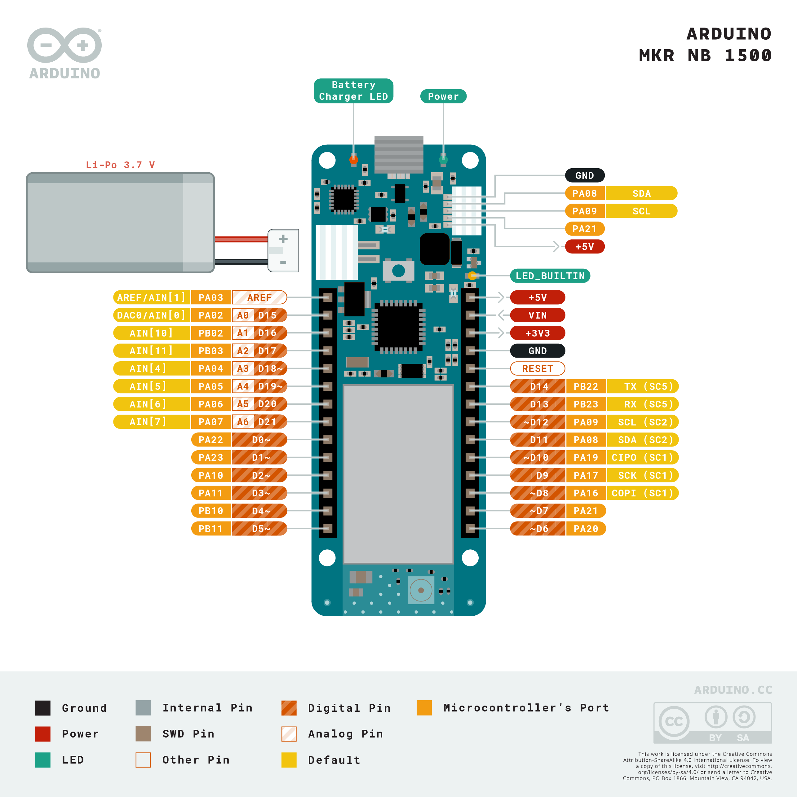
Overview
Add Narrowband communication to your project with the MKR NB 1500. It's the perfect choice for devices in remote locations without an Internet connection, or in situations in which power isn't available like on-field deployments, remote metering systems, solar-powered devices, or other extreme scenarios.
The board's main processor is a low power Arm® Cortex®-M0 32-bit SAMD21, like in the other boards within the Arduino MKR family. The Narrowband connectivity is performed with a module from u-blox, the SARA-R410M-02B, a low power chipset operating in the de different bands of the IoT LTE cellular range. On top of those, secure communication is ensured through the Microchip® ECC508 crypto chip. Besides that, the pcb includes a battery charger, and a connector for an external antenna.
This board is designed for global use, providing connectivity on LTE's Cat M1/NB1 bands 1, 2, 3, 4, 5, 8, 12, 13, 18, 19, 20, 25, 26, 28. Operators offering service in that part of the spectrum include: Vodafone, AT&T, T-Mobile USA, Telstra, and Verizon, among others.
Battery Power
Its USB port can be used to supply power (5V) to the board. It has a Li-Po charging circuit that allows the board to run on battery power or an external 5 volt source, charging the Li-Po battery while running on external power. Switching from one source to the other is done automatically.
Related Boards
If you are still deciding about the right wireless protocol for your solution, Arduino's MKR family has some alternatives to offer:
- MKR FOX 1200: for your EU solutions on Sigfox infrastructure. Visit its product page here.
- MKR WAN 1310: if you want to experiment with either LoRa® or LoRaWAN™. Read more here. We have also a LoRa® gateway if you are thiking of building your own infrastructure.
- MKR GSM 1400: when looking at global coverage, GSM / 3G is the world's most extended network. Visit its product page here. We also provide you with a bundle including the board and a SIM with a global data plan in case you need it.
Getting Started
The Getting Started section contains all the information you need to configure your board, use the Arduino Software (IDE), and start tinkering with coding and electronics. If you want to know more about Arduino’s MKRNB API, check this reference page.
Arduino IoT Cloud Compatible
Use your MKR board on Arduino's IoT Cloud, a simple and fast way to ensure secure communication for all of your connected Things.
TRY THE ARDUINO IOT CLOUD FOR FREE
*The MKR NB 1500 requires a SIM card to connect to the cloud, as it communicates over the mobile networks.
Need Help?
Check the Arduino Forum for questions about the Arduino Language, or how to make your own Projects with Arduino. Need any help with your board please get in touch with the official Arduino User Support as explained in our Contact Us page.
Warranty
You can find here your board warranty information.
Tech specs
The Arduino MKR NB 1500 is based on the SAMD21 microcontroller.
| Microcontroller | SAMD21 Cortex®-M0+ 32bit low power ARM MCU (datasheet) |
| Radio module | u-blox SARA-R410M-02B (datasheet / summary) |
| Secure Element | ATECC508 (datasheet) |
| Board Power Supply (USB/VIN) | 5V |
| Supported Battery | Li-Po Single Cell, 3.7V, 1500mAh Minimum |
| Circuit Operating Voltage | 3.3V |
| Digital I/O Pins | 8 |
| PWM Pins | 13 (0 .. 8, 10, 12, 18 / A3, 19 / A4) |
| UART | 1 |
| SPI | 1 |
| I2C | 1 |
| Analog Input Pins | 7 (ADC 8/10/12 bit) |
| Analog Output Pins | 1 (DAC 10 bit) |
| External Interrupts | 8 (0, 1, 4, 5, 6, 7, 8, 16 / A1, 17 / A2) |
| DC Current per I/O Pin | 7 mA |
| Flash Memory | 256 KB (internal) |
| SRAM | 32 KB |
| EEPROM | no |
| Clock Speed | 32.768 kHz (RTC), 48 MHz |
| LED_BUILTIN | 6 |
| Full-Speed USB Device and embedded Host | |
| Antenna gain | 2dB (bundled antenna at the Arduino Store) |
| Carrier frequency | LTE bands 1, 2, 3, 4, 5, 8, 12, 13, 18, 19, 20, 25, 26, 28 |
| Power class (radio) | LTE Cat M1 / NB1: Class 3 (23 dBm) |
| Data Rate (LTE M1 Half-Duplex) | UL 375 kbps / DL 300 kbps |
| Data Rate (LTE NB1 Full-Duplex) | UL 62.5 kbps / DL 27.2 kbps |
| Working region | Multiregion |
| Device Location | GNSS via modem |
| Power Consumption (LTE M1) | min 100 mA / max 190 mA |
| Power Consumption (LTE NB1) | min 60 mA / max 140 mA |
| SIM Card | MicroSIM (not included with the board) |
| Length | 67.64 mm |
| Width | 25 mm |
| Weight | 32 gr. |
Conformities
Resources for Safety and Products
Manufacturer Information
The production information includes the address and related details of the product manufacturer.
Arduino S.r.l.
Via Andrea Appiani, 25
Monza, MB, IT, 20900
https://www.arduino.cc/
Responsible Person in the EU
An EU-based economic operator who ensures the product's compliance with the required regulations.
Arduino S.r.l.
Via Andrea Appiani, 25
Monza, MB, IT, 20900
Phone: +39 0113157477
Email: support@arduino.cc
Documentation
OSH: Schematics
The MKR NB 1500 is open-source hardware! You can build your own board using the following files:
EAGLE FILES IN .ZIP SCHEMATICS IN .PDF
Pinout Diagram

Download the full pinout diagram as PDF here.
Interactive Board Viewer
Additional I2C Port
The MKR NB 1500 has an additional connector meant as an extension of the I2C bus. It's a small form factor 5-pin connector with 1.0 mm pitch. The mechanical details of the connector can be found in the connector's datasheet.
The I2C port, also referred to as the Eslov self-identification port within Arduino, comes with: SDA, SCL, GND, +5V, and an extra digital pin meant to send an alarm to the otherwise plain I2C devices connected to it. The pinout is shown in the following image:
If you are interested in designing your own modules for Arduino boards with this expansion port, the connector we suggest using is code: SHR-05V-S-B, also in the picture.
Learn more
Get Inspired

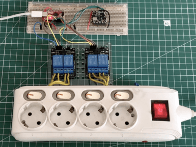
As Jallson Suryo discusses in his project, adding voice controls to our appliances typically involves an internet connection and a smart assistant device such as Amazon Alexa or Google Assistant. This means extra latency, security concerns, and increased expenses due to the additional hardware and bandwidth requirements. This is why he created a prototype based on an Arduino Nicla Voice that can provide power for up to four outlets using just a voice command. Suryo gathered a dataset by repeating the words “one," “two," “three," “four," “on," and “off” into his phone and then uploaded the recordings to an Edge Impulse project. From here, he split the files into individual words before rebalancing his dataset to ensure each label was equally represented. The classifier model was trained for keyword spotting and used Syntiant NDP120-optimal settings for voice to yield an accuracy of around 80%. Apart from the Nicla Voice, Suryo incorporated a Pro Micro board to handle switching the bank of relays on or off. When the Nicla Voice detects the relay number, such as “one” or “three," it then waits until the follow-up “on” or “off” keyword is detected. With both the number and state now known, it sends an I2C transmission to the accompanying Pro Micro which decodes the command and switches the correct relay. To see more about this voice-controlled power strip, be sure to check out Suryo’s Edge Impulse tutorial.
FAQs
Antenna
When purchased at the Arduino Store, the MKR NB 1500 comes bundled with an antenna that can be attached to the board using the existing micro UFL connector. It is possible to use other antennas using the appropriate pigtail.
When purchasing a different antenna than the one provided (or when making your own), please check that it is tuned for the frequency band in use in the LTE range. Also avoid placing your antenna in parallel to a ground plane like a large metallic surface.
Batteries, Pins and board LEDs
- Battery capacity: Rechargeable Li-Po. Please make sure the battery connector suits your battery. Minimum battery capacity should be 700 mAh, maximum 1500 mAh. The battery-charging chip is programmed with 4 hours of charging time, then it goes into automatic sleep mode. This will limit the amount of charge to max 1400 mAh per charging round. Beware: batteries below 700 mAh should NOT be charged with this board
- Battery connector: The connector is of type JST S2B-PH-SM4-TB(LF)(SN). Mating connector is JST PHR-2.
- Vin: This pin can be used to power the board with a regulated 5V source. If the power is fed through this pin, the USB power source is disconnected. This is the only way you can supply 5V (respect this value) to the board not using USB. This pin is an INPUT.
- 5V: This pin outputs 5V from the board when powered from the USB connector or from the VIN pin of the board. It is unregulated and the voltage is taken directly from the inputs. When powered from battery it supplies around 3.7 V.
- VCC: This pin outputs 3.3V through the on-board voltage regulator. This voltage is the same regardless the power source used (USB, Vin, and battery).
- LED ON: This LED is connected to the 5V input from either USB or VIN. It is not connected to the battery power, thus minimizing the impact on battery usage. It is therefore normal to have the board properly running on battery power without the LED ON being lit.
- Onboard LED: On MKR NB 1500 the onboard LED is connected to D6.
- Charge LED: This LED is driven by the charger chip that monitors the current drawn by the Li-Po battery while charging. Usually it will lit up when the board gets 5V from VIN or USB and the chip starts charging the Li-Po battery connected to the JST connector. Occassionally, this LED will blink at a frequency of about 2Hz. This is caused by any of the following conditions maintained for a long time (over 20 min):
- No battery is connected to JST connector.
- Overdischarged / damaged battery is connected. It can't be recharged.
- A fully charged battery is put through another unnecessary charging cycle.


