


Overview
Introduction
The Education Shield is a custom-made shield designed by Arduino Education, specially tailored for educational purposes to enable quick and easy learning while building projects. The shield is meant to be used in conjuction with the CTC Program. It connects to an Arduino 101 or UNO and extend their capabilities. The shield has a collection of features that make building small projects in or outside of the classroom easy:
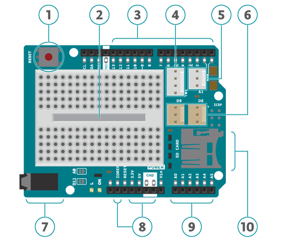
- Reset button. When this is pressed the program uploaded to the control board is restarted.
- Built in protoshield or used as a placement of breadboard.
- Digital input and output pins. Directly connected to the digital pins on the board.
- I2C connector.
- A1 3-pin header port: Analog out/in. This can also be used as a digital in/out.
- D6 and D9: digital 3-pin header ports connected to digital pin 6 and 9.
- Speaker plug:This is connected to digital pin 11.
- Ground and power pins. The voltage supply pin used in CTC is the IOREF pin. This pin outputs different voltages depending on the board (101 board: 3.3V, UNO board: 5V).
- Analog input/output pins.
- SD card reader/writer connected to digital pins 10 to 13.
Note:
- Avoid using analog A4 and A5. These have pull-up resistors connected to them and you should avoid using unless you know what you are doing.
- Do not use digital pins 4, 10, 11, 12 and 13 when using the micro SD card reader.
- Digital pins 9 to 13 cannot be used for capacitive sensors, these are connected to the SD card reader which has resistors and might therefore provide false readings.
- Digital pin 6, 9 and analog pin A1 are connected to component module ports. If the ports are used don’t use the corresponding pins.
- Digital pin 11 is connected to the audio socket. If the socket is in use don't use the pin.
Use Modules with simple connectors
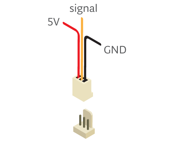
A simple 3 pin connector, that snaps in place, is used for all 3-pin modules. Here are some examples of components All these make connecting and prototyping easier through their simplified design: Push button modules, light sensor modules, and power LED modules.
If you’re trying to connect servos or other 3-pin modules, be sure about the direction of the connector so that GND is connected to GND, power to power and signal to signal. The color of a simple connector wire helps you remember it: red means power, orange or white means signal, and black means GND. Technically you can connect modules with simple connectors without 3-pin ports, as long as you plug the wires to the right pins.
Tech specs
|
Connectors |
1x I2C 4-pin connector* 1x 3-pin analog connector* 2x digital 3-pin connector* 1x pwm audiojack Plus extensions of the pins from the board. *Sullins Connector Solutions SWR25X series connector, commonly called “tinkerkit” connector” |
|
Interfaces with Arduino Board |
DIO |
|
Operating Voltage |
3.3 V (Arduino 101) or 5 V (Arduino Uno) |
|
PCB Size |
53 x 71.2 mm |
Conformities
Resources for Safety and Products
Manufacturer Information
The production information includes the address and related details of the product manufacturer.
Arduino S.r.l.
Via Andrea Appiani, 25
Monza, MB, IT, 20900
https://www.arduino.cc/
Responsible Person in the EU
An EU-based economic operator who ensures the product's compliance with the required regulations.
Arduino S.r.l.
Via Andrea Appiani, 25
Monza, MB, IT, 20900
Phone: +39 0113157477
Email: support@arduino.cc
Documentation
OSH: Schematics
The Arduino Education Shield is open-source hardware! You can build your own board using the following files:
Get Inspired
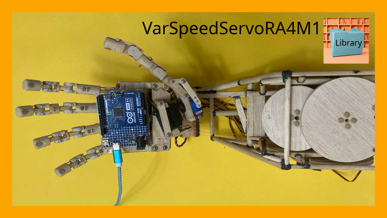
VarSpeedServoRA4M1 is a library for Arduino that enables precise control over servo motors, including speed, position, and movement sequences.
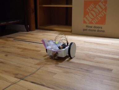
In robotics and several other disciplines, PID (proportional-integral-derivative) control is a way for systems with closed-loop feedback to adjust themselves according to sensor data without overshooting the target. Drones, for example, use PID control to remain stable without wild oscillations caused by over-correction. But implementing PID control can feel overwhelming, so Adam Soileau from element14 Presents built a simple robot for some experimentation. This robot’s only job is to drive forward until it sees a wall, then stop at a specific distance from that wall. That isn’t hard to achieve when a robot is moving at slow pace, because the code can tell the robot to stop moving the moment it reaches the target distance. But when moving fast, the robot has to take braking acceleration into account and that is much harder to predict. PID control is perfect for this situation, because it adjusts motor output in real-time according to the incoming sensor data. In this case, that sensor data comes from an ultrasonic rangefinder mounted to the front of the 3D-printed robot. An Arduino UNO R4 Minima board receives that data and controls the robot’s two motors through H-bridge drivers. That hardware is very straightforward so that Soileau could focus on the PID control. Tuning that is all about balancing the three constant values to get the desired performance. Soileau spent some time working on the Arduino sketch to get the PID control integrated and was eventually able to make the robot act like it should. If you’re interested in using PID control in your next robotics project, then Soileau's video should help you get started.


