


Overview
The Arduino 4 Relays Shield is a solution for driving high power loads that cannot be controlled by Arduino's digital IOs, due to the current and voltage limits of the controller. The Shield features four relays, each relay provides 2 pole changeover contacts (NO and NC); in order to increase the current limit of each output the 2 changeover contacts have been put in parallel. Four LEDs indicate the on/off state of each relay.
Getting Started
You can find in the Getting Started section all the information you need to configure your board, use the Arduino Software (IDE), and start tinker with coding and electronics..
Need Help?
- On the Software on the Arduino Forum
- On Projects on the Arduino Forum
- On the Product itself through our Customer Support
Tech specs
Features
| Thinker Kit interface | 2x TWI, 2x OUT, 2x IN |
| Interfaces with Arduino Board | DIO |
| Relays | 4 (60W) |
General
| Operating Voltage | 5 V |
| Current needs | 140 mA (with all releays on, about 35 mA each) |
| PCB Size | 53 x 68.5 mm |
| Weight | 0.044 Kg |
| Product Code | A000110 |
Conformities
Resources for Safety and Products
Manufacturer Information
The production information includes the address and related details of the product manufacturer.
Arduino S.r.l.
Via Andrea Appiani, 25
Monza, MB, IT, 20900
https://www.arduino.cc/
Responsible Person in the EU
An EU-based economic operator who ensures the product's compliance with the required regulations.
Arduino S.r.l.
Via Andrea Appiani, 25
Monza, MB, IT, 20900
Phone: +39 0113157477
Email: support@arduino.cc
Documentation
OSH: Schematics
The Arduino 4 Relays Shield is open-source hardware! You can build your own board using the following files:
EAGLE FILES IN .ZIP SCHEMATICS IN .PDF
Description
|
Operating Voltage |
5V |
|
Coil current consumption |
140 mA (with all releays on, about 35 mA each) |
|
Single pole chargeover contact maximum current |
@ 30 V DC 2A |
|
Maximum load voltage |
48 V |
|
Maximum switching capacity |
60 W |
Power
The shield doesn't need external power: it will be provided by the base board, through the 5V and 3.3V pins of the Arduino board used as base.
Input and Output
The relays are controlled by the following Arduino board pins: Relay 1 = Arduino pin 4 Relay 2 = Arduino pin 7 Relay 3 = Arduino pin 8 Relay 4 = Arduino pin 12 The shield features several TinkerKit input/output and communication interfaces. Connecting TinkerKit modules can simplify the creation of a project or a prototype. The on-board connectors are :
- 2 TinkerKit Inputs: IN2 and IN3 (in white), these connectors are routed to the Arduino A2 and A3 analog input pins.
- 2 TinkerKit Outputs: OUT5 and OUT6 (in orange), these connectors are routed to the Arduino PWM outputs on pins 5 and 6.
- 2 TinkerKit TWI: these connectors (4-pin in white) are routed on the Arduino TWI interface. Both connect to the same TWI interface to allow you to create a chain of TWI devices.
Physical Characteristics
The maximum length and width of the 4 Relays Shield PCB are 2.7 and 2.1 inches respectively. Four screw holes allow the Shield to be attached to a surface or case. Note that the distance between digital pins 7 and 8 is 160 mil (0.16"), not an even multiple of the 100 mil spacing of the other pins.
Compatible Boards
The shield is compatible with all the Arduino boards, 5V and also 3.3V standards.
Learn more
Get Inspired

Learn to set up an Arduino Nano RP2040 Connect to use MicroPython.
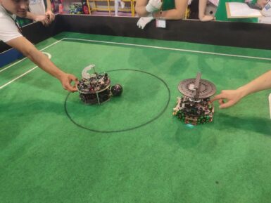
Team Ikaro is a vibrant group of high school students from the Pacinotti Archimede Institute in Rome, sharing a strong passion for electronics and turning heads in the world of robotics! Specializing in Soccer Lightweight games (where robot-soccer players compete to score goals on a miniature field), they clinched the first place at the Romecup 2024 and won Italy’s national Robocup in Verbania earlier this year – earning the right to compete in the world championships in Eindhoven, where they placed third in the SuperTeam competition. The brains behind the bots Utilizing the versatile Arduino Nano RP2040 Connect, the team has crafted highly efficient robots that feature ultrasound sensors, PCB boards, a camera, four motors, a solenoid kicker and omni-directional wheels, all meticulously assembled in the school’s FabLab. Mentored by professor Paolo Torda, Team Ikaro exemplifies the spirit of innovation and teamwork bringing together three talented students: Francesco D’Angelo, the team leader, focuses on system design and mechanics; Flavio Crocicchia, the software developer, ensures the robots’ brains are as sharp as possible; Lorenzo Addario specializes in camera software, making sure the robots can “see” and react swiftly on the field. Their combined efforts have led to a seamless integration of hardware and software, and established a foundation of passion and ambition for future success in their careers. Future goals After their first taste of global competition, Team Ikaro is determined to continue refining their robots, leveraging every bit of knowledge and experience they gain – whether in the classroom, lab, or live challenges. At Arduino, we are proud to sponsor such brilliant young minds and look forward to seeing what they will accomplish next!


