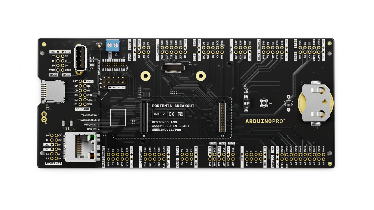
Overview
Portenta Breakout board is designed to help hardware engineers and makers to prototype and help test devices connections and capacity within the Portenta family boards (e.g. the Portenta H7).
It makes all high-density connectors’ signals individually accessible, making it quick and easy to connect and test external hardware components and devices as normally needed during development in the lab.
Target areas
Prototyping
Application examples
This product is designed to work alongside the Portenta family. Please check the Getting Started guide of your Portenta board.
Product Development: The Portenta Breakout board reduces development time for industrial grade solution automation based on the Portenta line.
Technical Education: The Portenta Breakout board can act as the first point of entry for technician education in industrial grade control and embedded systems.
Features
- Power ON Button
- Boot mode DIP switch
- Connectors
- USBA
- RJ45 up to 1Gb/s
- Micro SD card
- MIPI 20T JTAG with trace capability - Power
- CR2032 RTC Lithium Battery backup
- External power terminal block - I/O
- Break out all Portenta High Density connector signals
- Male/female HD connectors allow interposing breakout between Portenta and shield to debug signals - Compatibility
- Standard Portenta High Density connector pinout - Safety information
- Class A
Tech specs
| USB port | USBA |
| Ethernet | RJ45 up to 1Gb/s (Supported on Portenta X8 only) |
| Memory slot | Micro SD card |
| Debug | MIPI 20T JTAG with trace capability |
| Connectors | HD male/female |
| RTC power battery | CR2032 |
| Length | 164 mm |
| Width | 72 mm |
| Weight | 0,069 Kg |
Conformities
Resources for Safety and Products
Manufacturer Information
The production information includes the address and related details of the product manufacturer.
Arduino S.r.l.
Via Andrea Appiani, 25
Monza, MB, IT, 20900
https://www.arduino.cc/
Responsible Person in the EU
An EU-based economic operator who ensures the product's compliance with the required regulations.
Arduino S.r.l.
Via Andrea Appiani, 25
Monza, MB, IT, 20900
Phone: +39 0113157477
Email: support@arduino.cc
Documentation
Study how the Portenta Breakout Carrier works using following files:
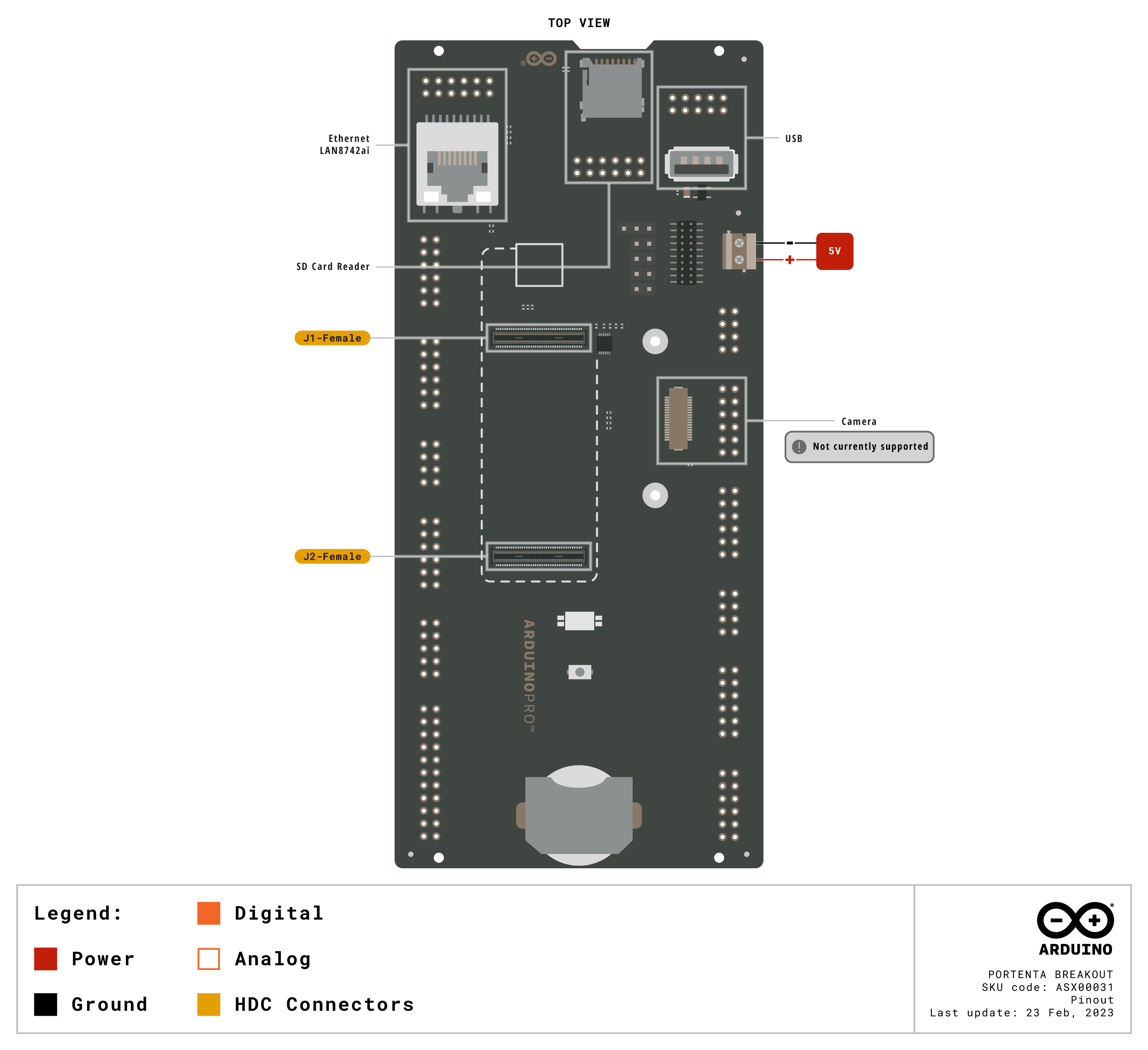
Pinout Diagram
Learn more about the portenta's pinout by reading the pinout documentation.

Download the full pinout diagram as PDF here.
Interactive Board Viewer
Learn more
Get Inspired

I have prepare home Automoation project using Arduino nano esp32

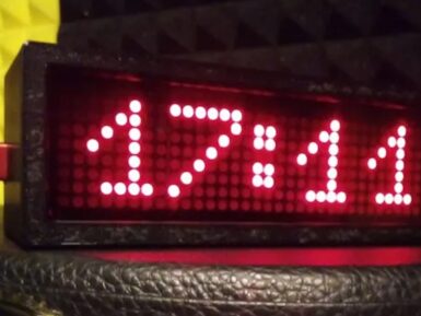
There are almost endless variations of clocks for sale on the internet today, but it is still easy to end up in a situation where you can't quite find a model with the style and features you want. Marco Zonca ended up with that problem while searching for a new clock to put in his music studio. Nothing on the market fit the bill, so he built this minimalist network-updated digital clock. Zonca wanted a simple design, the ability to adjust brightness, and NTP (Network Time Protocol) updates. There are clocks available with those features, but nothing in the style Zonca wanted. So he created the perfect clock for himself. It displays 24-hour time across a red LED matrix, lets the user control settings like brightness via Bluetooth® Low Energy communication, and always stays in sync with network time. An Arduino Nano ESP32 board, programmed through Arduino Web Editor, controls all of those functions. It mounts onto a custom PCB that Zonca designed for this clock. The PCB also hosts an 8×32 LED matrix display with MAX7219 driver. Three buttons on the PCB let the user select modes. The PCB fits into a black 3D-printed enclosure that reflects the overall minimalist style. Now Zonca has the perfect clock for his music studio. If you like the look of it, the sketch, PCB files, and 3D enclosure are all available on Hackster.io.


