


Overview
The Arduino 4 Relays Shield is a solution for driving high power loads that cannot be controlled by Arduino's digital IOs, due to the current and voltage limits of the controller. The Shield features four relays, each relay provides 2 pole changeover contacts (NO and NC); in order to increase the current limit of each output the 2 changeover contacts have been put in parallel. Four LEDs indicate the on/off state of each relay.
Getting Started
You can find in the Getting Started section all the information you need to configure your board, use the Arduino Software (IDE), and start tinker with coding and electronics..
Need Help?
- On the Software on the Arduino Forum
- On Projects on the Arduino Forum
- On the Product itself through our Customer Support
Tech specs
Features
| Thinker Kit interface | 2x TWI, 2x OUT, 2x IN |
| Interfaces with Arduino Board | DIO |
| Relays | 4 (60W) |
General
| Operating Voltage | 5 V |
| Current needs | 140 mA (with all releays on, about 35 mA each) |
| PCB Size | 53 x 68.5 mm |
| Weight | 0.044 Kg |
| Product Code | A000110 |
Conformities
Resources for Safety and Products
Manufacturer Information
The production information includes the address and related details of the product manufacturer.
Arduino S.r.l.
Via Andrea Appiani, 25
Monza, MB, IT, 20900
https://www.arduino.cc/
Responsible Person in the EU
An EU-based economic operator who ensures the product's compliance with the required regulations.
Arduino S.r.l.
Via Andrea Appiani, 25
Monza, MB, IT, 20900
Phone: +39 0113157477
Email: support@arduino.cc
Documentation
OSH: Schematics
The Arduino 4 Relays Shield is open-source hardware! You can build your own board using the following files:
EAGLE FILES IN .ZIP SCHEMATICS IN .PDF
Description
|
Operating Voltage |
5V |
|
Coil current consumption |
140 mA (with all releays on, about 35 mA each) |
|
Single pole chargeover contact maximum current |
@ 30 V DC 2A |
|
Maximum load voltage |
48 V |
|
Maximum switching capacity |
60 W |
Power
The shield doesn't need external power: it will be provided by the base board, through the 5V and 3.3V pins of the Arduino board used as base.
Input and Output
The relays are controlled by the following Arduino board pins: Relay 1 = Arduino pin 4 Relay 2 = Arduino pin 7 Relay 3 = Arduino pin 8 Relay 4 = Arduino pin 12 The shield features several TinkerKit input/output and communication interfaces. Connecting TinkerKit modules can simplify the creation of a project or a prototype. The on-board connectors are :
- 2 TinkerKit Inputs: IN2 and IN3 (in white), these connectors are routed to the Arduino A2 and A3 analog input pins.
- 2 TinkerKit Outputs: OUT5 and OUT6 (in orange), these connectors are routed to the Arduino PWM outputs on pins 5 and 6.
- 2 TinkerKit TWI: these connectors (4-pin in white) are routed on the Arduino TWI interface. Both connect to the same TWI interface to allow you to create a chain of TWI devices.
Physical Characteristics
The maximum length and width of the 4 Relays Shield PCB are 2.7 and 2.1 inches respectively. Four screw holes allow the Shield to be attached to a surface or case. Note that the distance between digital pins 7 and 8 is 160 mil (0.16"), not an even multiple of the 100 mil spacing of the other pins.
Compatible Boards
The shield is compatible with all the Arduino boards, 5V and also 3.3V standards.
Learn more
Get Inspired
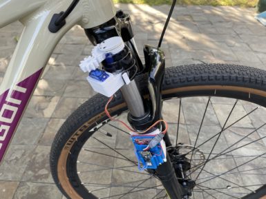
Arduino based bicycle movement sensor and GPS tracker.
… magnetic reed switch, but building the game himself in Unity. He had to construct and animate models for himself, the bike, and the scenery. After adding an AI and ranking system to the game, he was able to successfully race within the virtual environment on a real bike. Responsive LED system Motivated by the desire for a more advanced lighting system while on her nighttime bike rides, Natasha (TechnoChic) decided to affix strips of NeoPixel LEDs all over her bike that could react to music in real-time. The LEDs are controlled by an Arduino Nano 33 IoT that is, in turn, connected to her boombox via a 3.5mm audio jack for reading the audio signal. Two additional Nano 33 IoT boards were used for the wheels, along with more NeoPixels and batteries for each. GPS tracker Bicycle theft has been rapidly increasing over the last couple of years, which is why being able to recover a stolen bike has become vital. Johan’s bike tracker project contains an Arduino MKR GSM 1400 which reads motion data from an IMU and uses it to determine if the bike has moved when it is not supposed to. Once movement is detected, the board reads GPS data from a MKR GPS Shield and sends it over an LTE data connection in real-time so that the bike can be found. Integrated safety features The majority of mountain bikes lack useful safety features such as integrated lights, turn signals, and speed tracking, which is why Collin Wentzien embarked on his “(not so) electric bike” project. He built a series of features, including automatic brake/turn lights, a headlight, and an electronic horn with the goal of improving safety. Furthermore, his bike also got a bike computer upgrade which contains an Arduino Mega, GPS module, and dual screens for displaying relevant telemetry data. Speedometer display After losing the display unit for her bike computer, Element14 Presents host Katie wanted to replace it with a DIY version that tracked the current speed


