


Overview
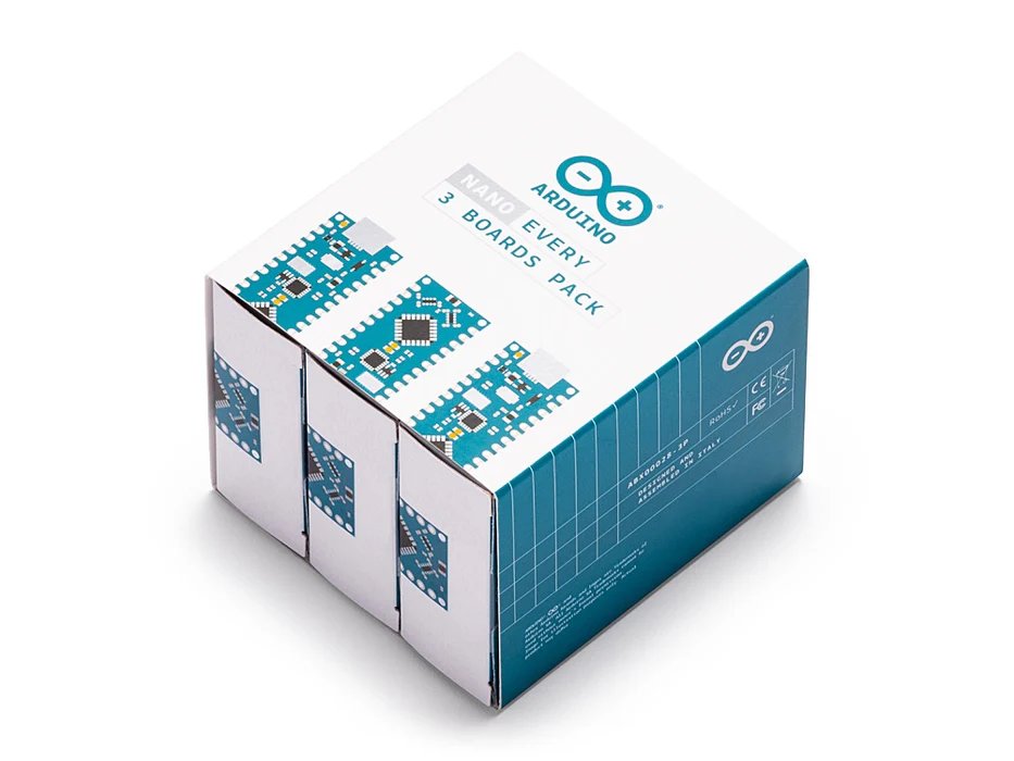
The Nano Every is Arduino’s 5V compatible board in the smallest available form factor: 45x18mm!
The Arduino Nano is the preferred board for many projects requiring a small and easy to use microcontroller board. One example is low cost robotics, where the Nano is broadly used. If you are in the situation of needing many boards for your classroom, or if you need to present a complex prototype with many functional blocks, this pack will offer you exactly what you need: a series of Arduino Nano Every boards at a discounted price.
The Arduino Nano Every is an evolution of the traditional Arduino Nano, but featuring a lot more powerful processor, the ATMega4809. This will allow you making larger programs than with the Arduino Uno (it has 50% more program memory), and with a lot more variables (the RAM is 200% bigger).
The pack is available in two sizes with either 3 or 6 boards of Arduino Nano Every without headers. Whether you want to minimize the size of your prototypes or share the joy of electronics with your friends, this is the best option you will find.
Get to Know More
To know more about the history of the Nano Every don’t miss the interview with Dario Pennisi, Arduino’s hardware and firmware development manager, who led the development of this board.
Getting Started
The Getting Started section contains all the information you need to configure your board, use the Arduino Software (IDE), and start tinkering with coding and electronics.
Need Help?
Check the Arduino Forum for questions about the Arduino Language, or how to make your own . For any issues when acquiring products at the Arduino store, contact our Store Customer Support. If you purchased the Nano Every Pack and found any issues get in touch with the Official Arduino User Support as explained at our Contact Page.
Warranty
You can find here your board warranty information.
Tech specs
The Arduino Nano Every is based on the ATMega4809 microcontroller.
| Microcontroller | ATMega4809 (datasheet) |
| Operating Voltage | 5V |
| Input Voltage (limit) | 21V |
| DC Current per I/O Pin | 20 mA |
| DC Current for 3.3V Pin | 50 mA |
| Clock Speed | 20MHz |
| CPU Flash Memory | 48KB (ATMega4809) |
| SRAM | 6KB (ATMega4809) |
| EEPROM | 256byte (ATMega4809) |
| PWM Pins | 5 (D3, D5, D6, D9, D10) |
| UART | 1 |
| SPI | 1 |
| I2C | 1 |
| Analog Input Pins | 8 (ADC 10 bit) |
| Analog Output Pins | Only through PWM (no DAC) |
| External Interrupts | all digital pins |
| LED_BUILTIN | 13 |
| USB | Uses the ATSAMD11D14A (datasheet) |
| Length | 45 mm |
| Width | 18 mm |
| Weight | 5 gr (with headers) |
Conformities
Resources for Safety and Products
Manufacturer Information
The production information includes the address and related details of the product manufacturer.
Arduino S.r.l.
Via Andrea Appiani, 25
Monza, MB, IT, 20900
https://www.arduino.cc/
Responsible Person in the EU
An EU-based economic operator who ensures the product's compliance with the required regulations.
Arduino S.r.l.
Via Andrea Appiani, 25
Monza, MB, IT, 20900
Phone: +39 0113157477
Email: support@arduino.cc
Documentation
OSH: Schematics
The Arduino Nano Every is open-source hardware! You can build your own board using the following files:
EAGLE FILES IN .ZIP SCHEMATICS IN .PDF
Pinout Diagram
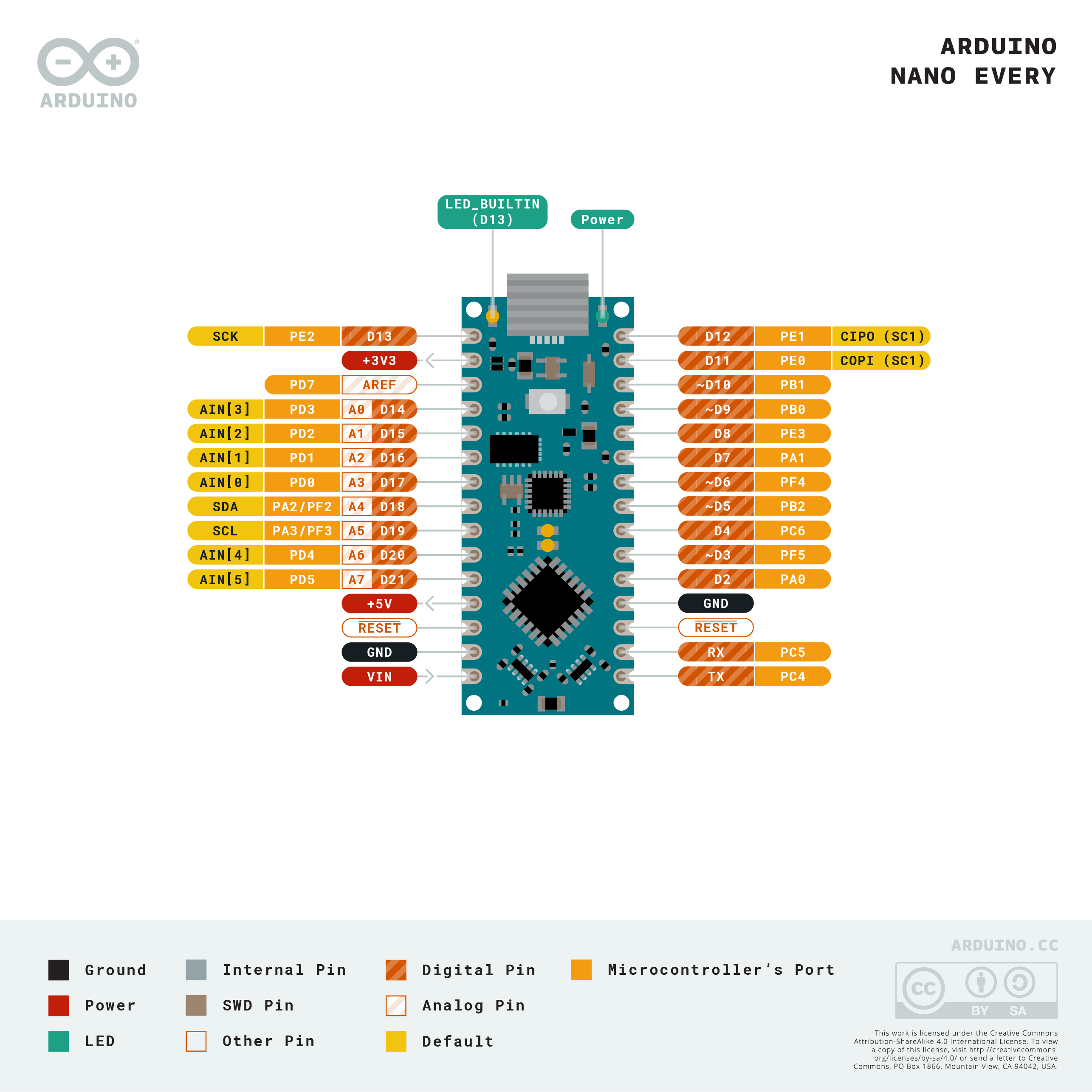
Download the full pinout diagram as PDF here.
Download the Fritzing file here.
Learn more
Get Inspired
If you’re interested in embedded machine learning (TinyML) on the Arduino Nano 33 BLE Sense, you’ll have found a ton of on-board sensors — digital microphone, accelerometer, gyro, magnetometer, light, proximity, temperature, humidity and color — but realized that for vision you need to attach an external camera. In this article, we will show you how to get image data from a low-cost VGA camera module. We’ll be using the Arduino_OVD767x library to make the software side of things simpler. Hardware setup To get started, you will need: Arduino Nano 33 BLE Sense with headersOV7670 CMOS VGA Camera Module 16x female to female jumper wiresA microUSB cable to connect to your Arduino You can of course get a board without headers and solder instead, if that's your preference. The one downside to this setup is that (in module form) there are a lot of jumpers to connect. It’s not hard but you need to take care to connect the right cables at either end. You can use tape to secure the wires once things are done, lest one comes loose. You need to connect the wires as follows: Software setup First, install the Arduino IDE or register for Arduino Create tools. Once you install and open your environment, the camera library is available in the library manager. Install the Arduino IDE or register for Arduino CreateTools > Manage Libraries and search for the OV767 libraryPress the Install button Now, we will use the example sketch to test the cables are connected correctly: Examples > Arduino_OV767X > CameraCaptureRawBytesUncomment (remove the //) from line 48 to display a test pattern Compile and upload to your board Your Arduino is now outputting raw image binary over serial. To view this as an image we’ve included a special application to view the image output from the camera using Processing. Processing is a simple programming environment that was created by graduate students at MIT Media Lab to make
FAQs
Batteries, Pins and board LEDs
- Batteries: the Nano Every has no battery connector, nor charger. You can connect any external battery of your liking as long as you respect the voltage limits of the board.
- Vin: This pin can be used to power the board with a DC voltage source. If the power is fed through this pin, the USB power source is disconnected. This pin is an INPUT. Respect the voltage limits to assure the proper functionality of the board.
- 5V: This pin outputs 5V from the board when powered from the USB connector or from the VIN pin of the board.
- 3.3V: This pin outputs 3.3V through the on-board voltage regulator.
- LED ON: This LED is connected to the 5V input from either USB or VIN.


