


Overview
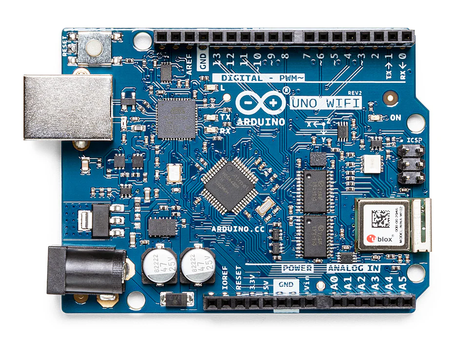
The Arduino UNO WiFi Rev.2 is the easiest point of entry to basic IoT with the standard form factor of the UNO family. Whether you are looking at building a sensor network connected to your office or home router, or if you want to create a Bluetooth® Low Energy device sending data to a cellphone, the Arduino UNO WiFi Rev.2 is your one-stop-solution for many of the basic IoT application scenarios.
Add this board to a device and you'll be able to connect it to a WiFi network, using its secure ECC608 crypto chip accelerator. The Arduino Uno WiFi is functionally the same as the Arduino Uno Rev3, but with the addition of WiFi / Bluetooth® and some other enhancements. It incorporates the brand new ATmega4809 8-bit microcontroller from Microchip and has an onboard IMU (Inertial Measurement Unit) LSM6DS3TR.
The Wi-Fi Module is a self-contained SoC with integrated TCP/IP protocol stack that can provide access to a Wi-Fi network, or act as an access point. It is the u-blox NINA-W102 and (here) you find the datasheet.
The Arduino UNO WiFi Rev.2 has 14 digital input/output pins—5 can be used as PWM outputs—6 analog inputs, a USB connection, a power jack, an ICSP header, and a reset button. It contains everything needed to support the microcontroller. Simply connect it to a computer with a USB cable or power it with an AC adapter or battery to get started.
Compatibility
This board has the Microchip ATmega4809 microcontroller, but thanks to the compatibility layer included in the core, you can run all the sketches made for the UNO's ATmega328P microconntroller on the ATmega4809. You can find more information about the usage of this mode in the Getting Started page of the Arduino UNO WiFi Rev.2.
Bluetooth® and Bluetooth® Low Energy
The communications chipset on the Arduino UNO WiFi Rev.2 can be both a Bluetooth® and Bluetooth® Low Energy client and host device. Something pretty unique in the world of microcontroller platforms. If you want to see how easy it is to create a Bluetooth® central or a peripheral device, explore the examples at our ArduinoBLE library.
We Make it Open for you to Hack Along
The Arduino UNO WiFi Rev.2 is a dual processor device that invites for experimentation. Hacking the WiFiNINA module allows you to, for example, make use of both WiFi and Bluetooth® and Bluetooth® Low Energy at once on the board. Yet another possibility is having a super-lightweight version of linux running on the module, while the main microcontroller controls low level devices like motors, or screens. These experimental techniques, require advanced hacking on your side. They are possible via modifying the module's firmware that you can find at our github repositories.
BEWARE: this kind of hacking breaks the certification of your WiFiNINA module, do it at your own risk.
Related Boards
If you are looking at upgrading from previous Arduino designs, or if you are just interested in boards with similar functionality, at Arduino you can find:
- MKR WiFi 1010: the small form factor version of the Arduino UNO WiFi Rev.2, with a battery connector and an additional I2C port. Read more here.
- Nano 33 IoT: if you need an even smaller form factor, this board sacrifices the battery connector, but the basic functionality is essentially the same. Visit its product page here.
- MKR WiFi 1000: can only run WiFi applications, as it includes a different chipset than the MKR WiFi 1010. Read more about it here.
Getting Started
The Getting Started section contains all the information you need to configure your board, use the Arduino Software (IDE), and start tinkering with coding and electronics.
Need Help?
Check the Arduino Forum for questions about the Arduino Language, or how to make your own Projects with Arduino. Need any help with your board please get in touch with the official Arduino User Support as explained in our Contact Us page.
Warranty
You can find here your board warranty information.
Tech specs
| Microcontroller | ATmega4809 (datasheet) |
| Operating Voltage | 5V |
| Input Voltage (recommended) | 6 - 20V |
| Digital I/O Pins | 14 — 5 Provide PWM Output |
| PWM Digital I/O Pins | 5 |
| Analog Input Pins | 6 |
| DC Current per I/O Pin | 20 mA |
| DC Current for 3.3V Pin | 50 mA |
| Flash Memory | 48 KB (ATmega4809) |
| SRAM | 6,144 Bytes (ATmega4809) |
| EEPROM | 256 Bytes (ATmega4809) |
| Clock Speed | 16 MHz |
| Radio module | u-blox NINA-W102 (datasheet) |
| Secure Element | ATECC608A (datasheet) |
| Inertial Measurement Unit | LSM6DS3TR (datasheet) |
| LED_BUILTIN | 25 |
| Length | 68.6 mm |
| Width | 53.4 mm |
| Weight | 25 g |
Conformities
Resources for Safety and Products
Manufacturer Information
The production information includes the address and related details of the product manufacturer.
Arduino S.r.l.
Via Andrea Appiani, 25
Monza, MB, IT, 20900
https://www.arduino.cc/
Responsible Person in the EU
An EU-based economic operator who ensures the product's compliance with the required regulations.
Arduino S.r.l.
Via Andrea Appiani, 25
Monza, MB, IT, 20900
Phone: +39 0113157477
Email: support@arduino.cc
Documentation
OSH: Schematics
The UNO WIFi REV2 is open-source hardware! You can build your own board using the following files:
EAGLE FILES IN .ZIP SCHEMATICS IN .PDF
Pinout Diagram
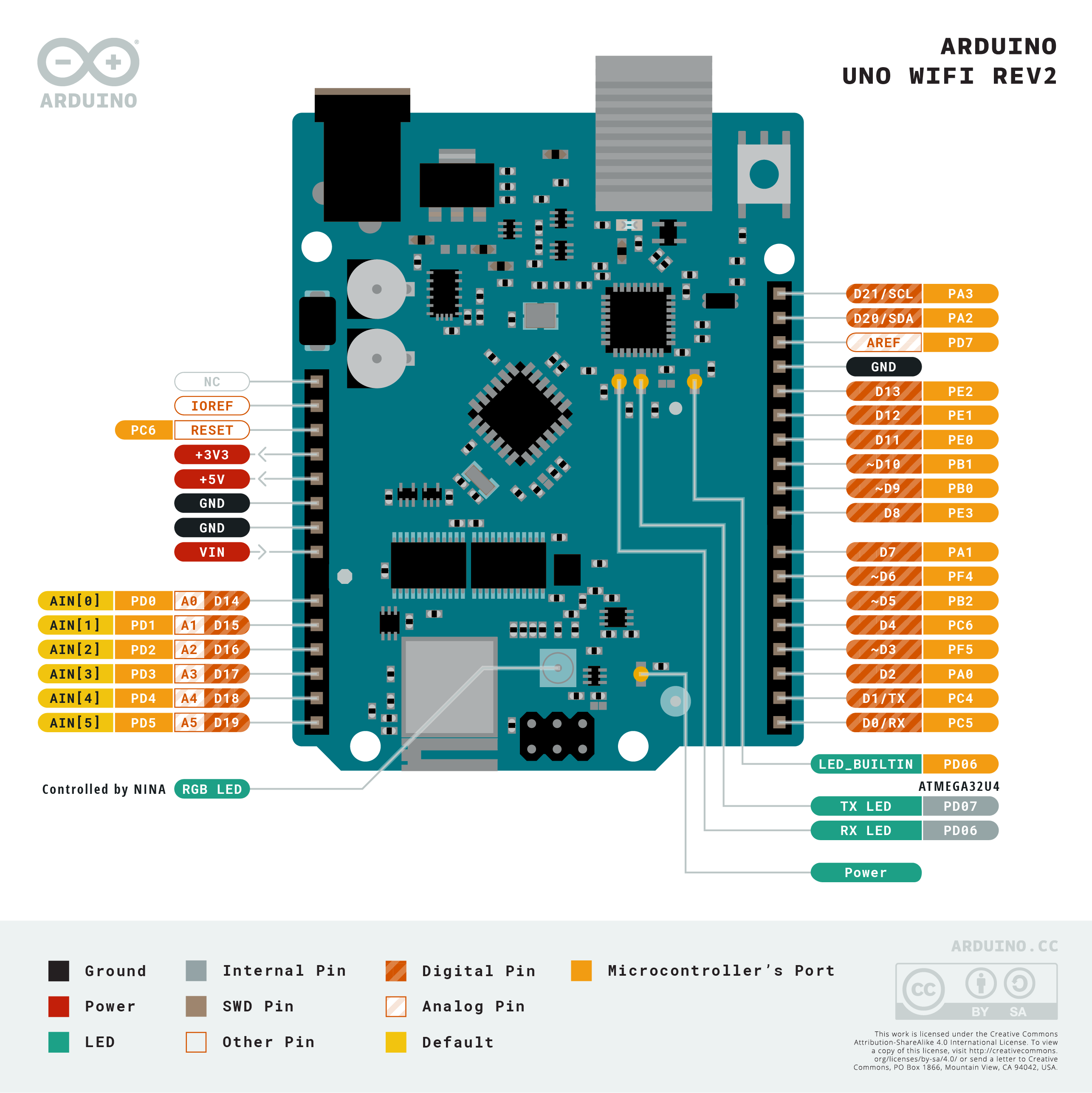
Download the full pinout diagram as PDF here.
Interactive Board Viewer
Learn more
Get Inspired
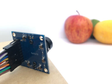
If you’re interested in embedded machine learning (TinyML) on the Arduino Nano 33 BLE Sense, you’ll have found a ton of on-board sensors — digital microphone, accelerometer, gyro, magnetometer, light, proximity, temperature, humidity and color — but realized that for vision you need to attach an external camera. In this article, we will show you how to get image data from a low-cost VGA camera module. We’ll be using the Arduino_OVD767x library to make the software side of things simpler. Hardware setup To get started, you will need: Arduino Nano 33 BLE Sense with headersOV7670 CMOS VGA Camera Module 16x female to female jumper wiresA microUSB cable to connect to your Arduino You can of course get a board without headers and solder instead, if that's your preference. The one downside to this setup is that (in module form) there are a lot of jumpers to connect. It’s not hard but you need to take care to connect the right cables at either end. You can use tape to secure the wires once things are done, lest one comes loose. You need to connect the wires as follows: Software setup First, install the Arduino IDE or register for Arduino Create tools. Once you install and open your environment, the camera library is available in the library manager. Install the Arduino IDE or register for Arduino CreateTools > Manage Libraries and search for the OV767 libraryPress the Install button Now, we will use the example sketch to test the cables are connected correctly: Examples > Arduino_OV767X > CameraCaptureRawBytesUncomment (remove the //) from line 48 to display a test pattern Compile and upload to your board Your Arduino is now outputting raw image binary over serial. To view this as an image we’ve included a special application to view the image output from the camera using Processing. Processing is a simple programming environment that was created by graduate students at MIT Media Lab to make


