


Overview
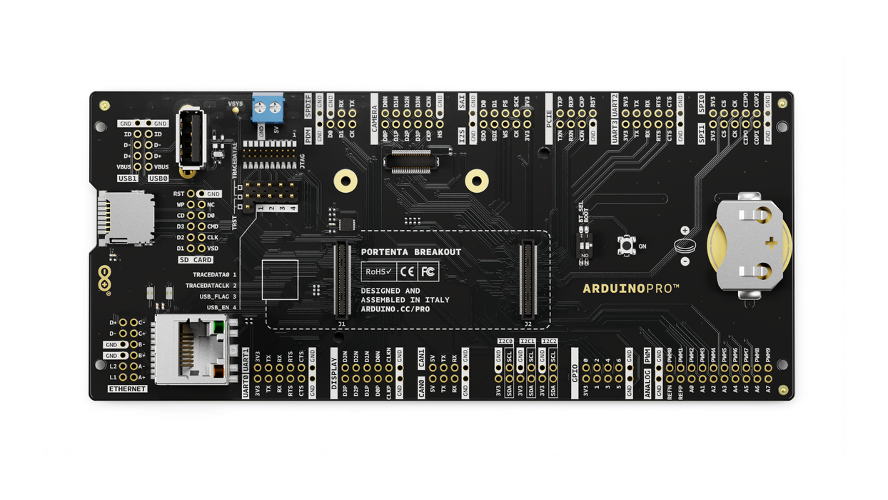
Portenta Breakout board is designed to help hardware engineers and makers to prototype and help test devices connections and capacity within the Portenta family boards (e.g. the Portenta H7).
It makes all high-density connectors’ signals individually accessible, making it quick and easy to connect and test external hardware components and devices as normally needed during development in the lab.
Target areas
Prototyping
Application examples
This product is designed to work alongside the Portenta family. Please check the Getting Started guide of your Portenta board.
Product Development: The Portenta Breakout board reduces development time for industrial grade solution automation based on the Portenta line.
Technical Education: The Portenta Breakout board can act as the first point of entry for technician education in industrial grade control and embedded systems.
Features
- Power ON Button
- Boot mode DIP switch
- Connectors
- USBA
- RJ45 up to 1Gb/s
- Micro SD card
- MIPI 20T JTAG with trace capability - Power
- CR2032 RTC Lithium Battery backup
- External power terminal block - I/O
- Break out all Portenta High Density connector signals
- Male/female HD connectors allow interposing breakout between Portenta and shield to debug signals - Compatibility
- Standard Portenta High Density connector pinout - Safety information
- Class A
Tech specs
| USB port | USBA |
| Ethernet | RJ45 up to 1Gb/s (Supported on Portenta X8 only) |
| Memory slot | Micro SD card |
| Debug | MIPI 20T JTAG with trace capability |
| Connectors | HD male/female |
| RTC power battery | CR2032 |
| Length | 164 mm |
| Width | 72 mm |
| Weight | 0,069 Kg |
Conformities
Resources for Safety and Products
Manufacturer Information
The production information includes the address and related details of the product manufacturer.
Arduino S.r.l.
Via Andrea Appiani, 25
Monza, MB, IT, 20900
https://www.arduino.cc/
Responsible Person in the EU
An EU-based economic operator who ensures the product's compliance with the required regulations.
Arduino S.r.l.
Via Andrea Appiani, 25
Monza, MB, IT, 20900
Phone: +39 0113157477
Email: support@arduino.cc
Documentation
Study how the Portenta Breakout Carrier works using following files:
Pinout Diagram
Learn more about the portenta's pinout by reading the pinout documentation.
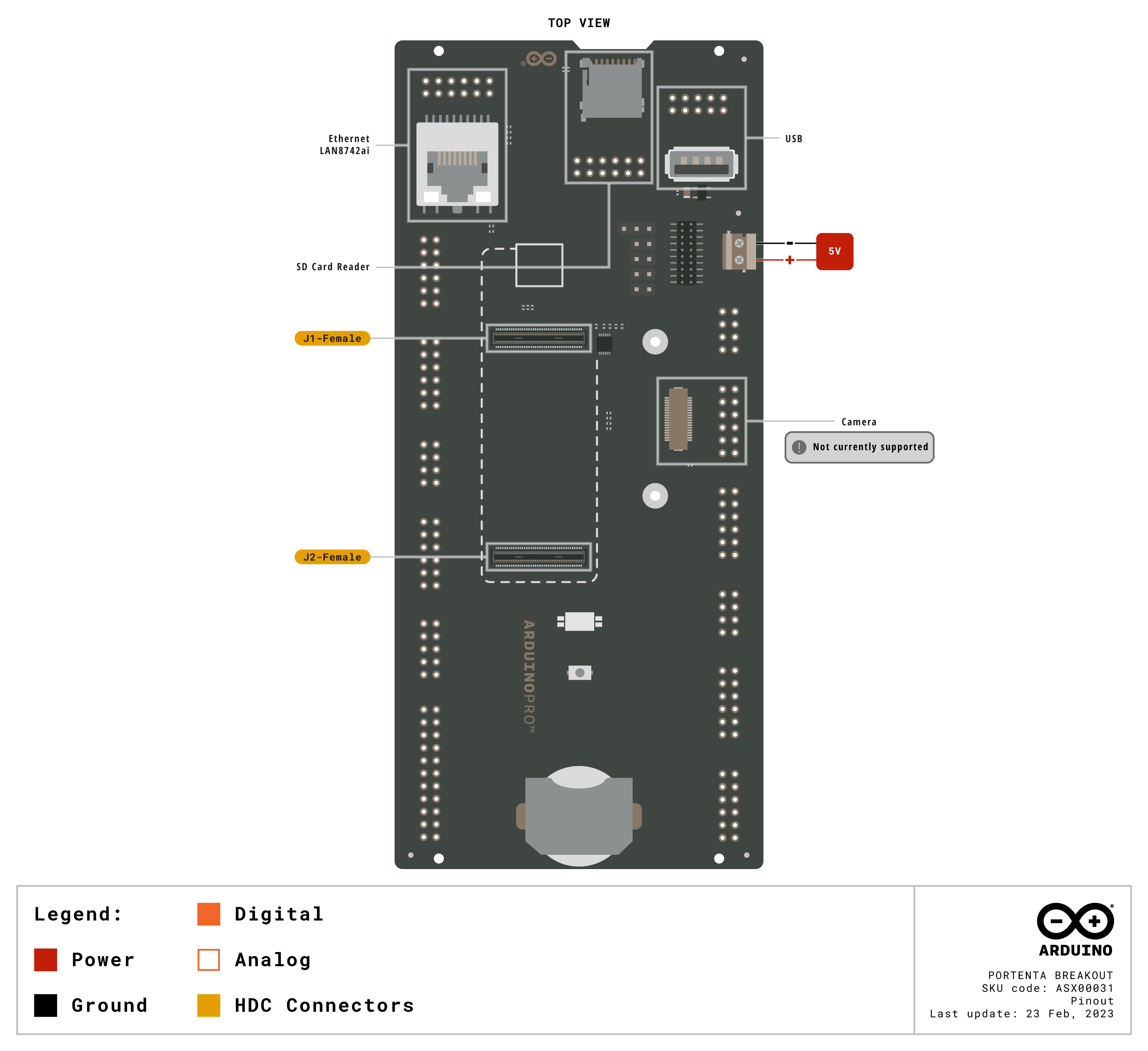
Download the full pinout diagram as PDF here.
Interactive Board Viewer
Learn more
Get Inspired
Robot using Arduino Nano 33 BLE Camera Shield.
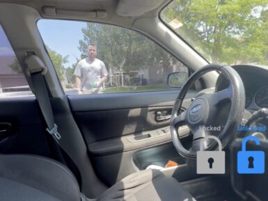
A lot of newer cars have a really nifty feature called “proximity unlock,” which automatically unlocks the doors when the driver approaches while carrying their key fob. When paired with a push-to-start ignition switch, the driver never has to take their keys out of their pocket. But Nick’s 2004 Subaru STI is too old to have come with that feature from the factory, so he used a couple of Arduino boards to create a DIY proximity unlock system. Car manufacturers need to pay serious attention to security when designing their access and ignition systems, but Nick had a bit more freedom. It is unlikely that any thieves would suspect his car of possessing a feature like this and so they wouldn’t even bother trying to hack it. Nick’s proximity unlock works by evaluating the received signal strength indicator (RSSI) of Bluetooth® Low Energy connection. If all else is equal, RSSI is inversely proportional to distance and that makes it useful for rough proximity detection. An Arduino Nano 33 BLE inside the car unlocks the doors when it has an active BLE connection with an RSSI over a set threshold. It unlocks the doors by shorting the switch with a 12V relay and it receives power from the car’s 12V system through a buck converter. The driver-carried device (equivalent to a key fob) can be either another Nano 33 BLE or Nick’s smartphone. In fact, it can be any device with a BLE adapter, so long as it can connect to the in-car Arduino with the proper device name. Now, Nick can enjoy his classic car and the convenience of proximity unlock.


