


Overview
The Arduino Nano is a small, complete, and breadboard-friendly board based on the ATmega328 (Arduino Nano 3.x). It has more or less the same functionality of the Arduino Duemilanove, but in a different package. It lacks only a DC power jack, and works with a Mini-B USB cable instead of a standard one.
Related Boards
If you are looking for a Nano board with similar functionality but also provide additional features, check:
Getting Started
Find inspiration for your projects with the Nano board from our tutorial platform Project Hub.
You can find in the Getting Started with Arduino Nano section all the information you need to configure your board, use the Arduino Software (IDE), and start tinkering with coding and electronics.
From the Tutorials section you can find examples from libraries and built-in sketches as well other useful information to expand your knowledge of the Arduino hardware and software.
Need Help?
Check the Arduino Forum for questions about the Arduino Language, or how to make your own Projects with Arduino. Need any help with your board please get in touch with the official Arduino User Support as explained in our Contact Us page.
Warranty
You can find here your board warranty information.
Tech specs
| Microcontroller | ATmega328 |
| Architecture | AVR |
| Operating Voltage | 5 V |
| Flash Memory | 32 KB of which 2 KB used by bootloader |
| SRAM | 2 KB |
| Clock Speed | 16 MHz |
| Analog IN Pins | 8 |
| EEPROM | 1 KB |
| DC Current per I/O Pins | 20 mA (I/O Pins) |
| Input Voltage | 7-12V |
| Digital I/O Pins | 22 (6 of which are PWM) |
| PWM Output | 6 |
| Power Consumption | 19 mA |
| PCB Size | 18 x 45 mm |
| Weight | 7 g |
| Product Code | A000005 |
Conformities
Resources for Safety and Products
Manufacturer Information
The production information includes the address and related details of the product manufacturer.
Arduino S.r.l.
Via Andrea Appiani, 25
Monza, MB, IT, 20900
https://www.arduino.cc/
Responsible Person in the EU
An EU-based economic operator who ensures the product's compliance with the required regulations.
Arduino S.r.l.
Via Andrea Appiani, 25
Monza, MB, IT, 20900
Phone: +39 0113157477
Email: support@arduino.cc
Documentation
OSH: Schematics
The Arduino Nano is open-source hardware! You can build your own board using the following files:
EAGLE FILES IN .ZIP SCHEMATICS IN .PDF BOARD SIZE IN .PDF
Pinout Diagram
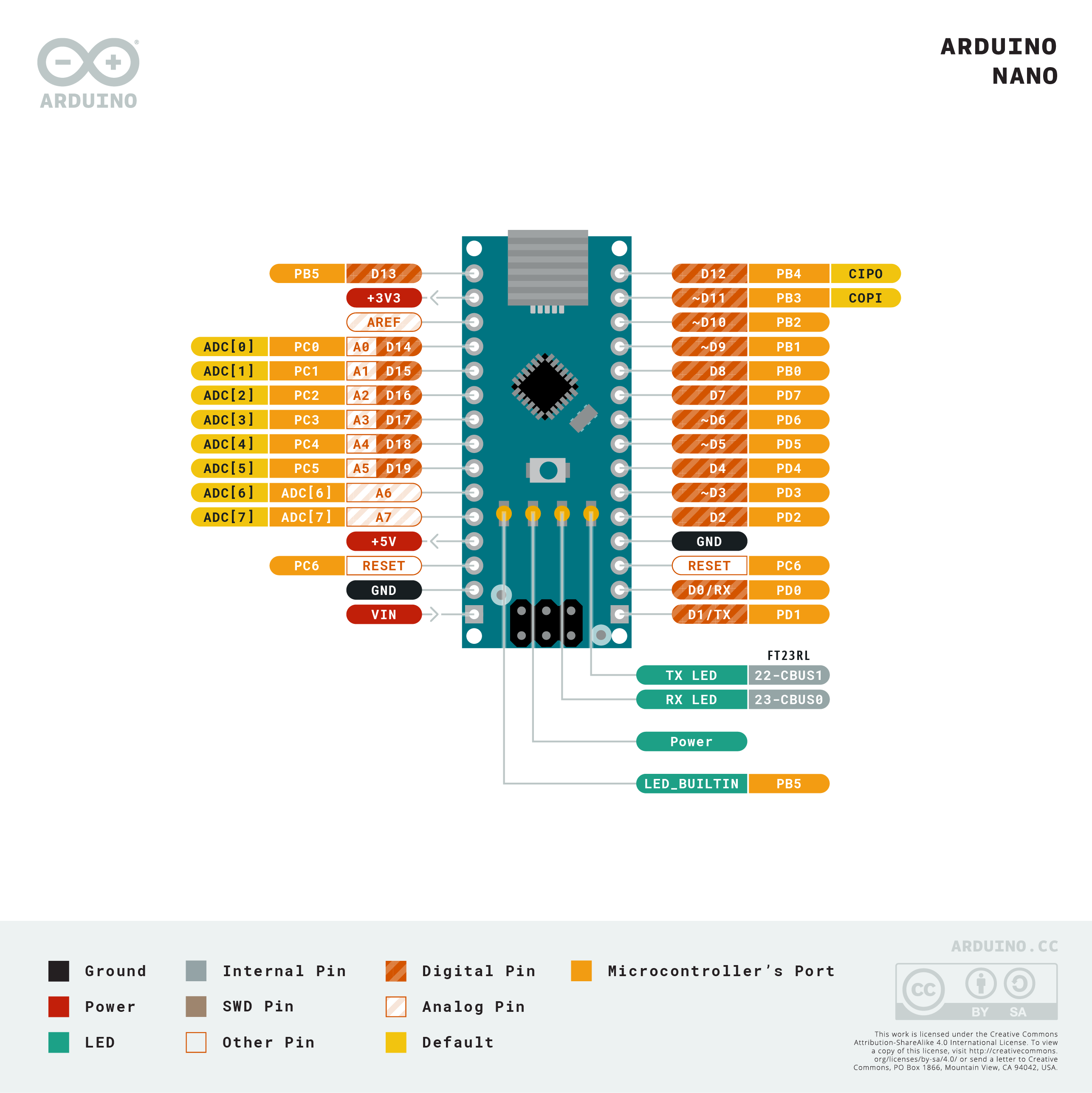
Download the full pinout diagram as PDF here.
Learn more
Get Inspired
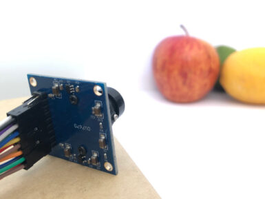
If you’re interested in embedded machine learning (TinyML) on the Arduino Nano 33 BLE Sense, you’ll have found a ton of on-board sensors — digital microphone, accelerometer, gyro, magnetometer, light, proximity, temperature, humidity and color — but realized that for vision you need to attach an external camera. In this article, we will show you how to get image data from a low-cost VGA camera module. We’ll be using the Arduino_OVD767x library to make the software side of things simpler. Hardware setup To get started, you will need: Arduino Nano 33 BLE Sense with headersOV7670 CMOS VGA Camera Module 16x female to female jumper wiresA microUSB cable to connect to your Arduino You can of course get a board without headers and solder instead, if that's your preference. The one downside to this setup is that (in module form) there are a lot of jumpers to connect. It’s not hard but you need to take care to connect the right cables at either end. You can use tape to secure the wires once things are done, lest one comes loose. You need to connect the wires as follows: Software setup First, install the Arduino IDE or register for Arduino Create tools. Once you install and open your environment, the camera library is available in the library manager. Install the Arduino IDE or register for Arduino CreateTools > Manage Libraries and search for the OV767 libraryPress the Install button Now, we will use the example sketch to test the cables are connected correctly: Examples > Arduino_OV767X > CameraCaptureRawBytesUncomment (remove the //) from line 48 to display a test pattern Compile and upload to your board Your Arduino is now outputting raw image binary over serial. To view this as an image we’ve included a special application to view the image output from the camera using Processing. Processing is a simple programming environment that was created by graduate students at MIT Media Lab to make
FAQs
Power
The Arduino Nano can be powered via the Mini-B USB connection, 6-20V unregulated external power supply (pin 30), or 5V regulated external power supply (pin 27). The power source is automatically selected to the highest voltage source.
Memory
The ATmega328 has 32 KB, (also with 2 KB used for the bootloader. The ATmega328 has 2 KB of SRAM and 1 KB of EEPROM.
Input and Output
Each of the 14 digital pins on the Nano can be used as an input or output, using pinMode(), digitalWrite(), and digitalRead() functions. They operate at 5 volts. Each pin can provide or receive a maximum of 40 mA and has an internal pull-up resistor (disconnected by default) of 20-50 kOhms. In addition, some pins have specialized functions:
- Serial: 0 (RX) and 1 (TX). Used to receive (RX) and transmit (TX) TTL serial data. These pins are connected to the corresponding pins of the FTDI USB-to-TTL Serial chip.
- External Interrupts: 2 and 3. These pins can be configured to trigger an interrupt on a low value, a rising or falling edge, or a change in value. See the attachInterrupt() function for details.
- PWM: 3, 5, 6, 9, 10, and 11. Provide 8-bit PWM output with the analogWrite() function.
- SPI: 10 (SS), 11 (MOSI), 12 (MISO), 13 (SCK). These pins support SPI communication, which, although provided by the underlying hardware, is not currently included in the Arduino language.
- LED: 13. There is a built-in LED connected to digital pin 13. When the pin is HIGH value, the LED is on, when the pin is LOW, it's off.
The Nano has 8 analog inputs, each of which provide 10 bits of resolution (i.e. 1024 different values). By default they measure from ground to 5 volts, though is it possible to change the upper end of their range using the analogReference() function. Analog pins 6 and 7 cannot be used as digital pins. Additionally, some pins have specialized functionality:
- I2C: A4 (SDA) and A5 (SCL). Support I2C (TWI) communication using the Wire library (documentation on the Wiring website).
There are a couple of other pins on the board:
- AREF. Reference voltage for the analog inputs. Used with analogReference().
- Reset. Bring this line LOW to reset the microcontroller. Typically used to add a reset button to shields which block the one on the board.
Communication
The Arduino Nano has a number of facilities for communicating with a computer, another Arduino, or other microcontrollers. The ATmega328 provide UART TTL (5V) serial communication, which is available on digital pins 0 (RX) and 1 (TX). An FTDI FT232RL on the board channels this serial communication over USB and the FTDI drivers (included with the Arduino software) provide a virtual com port to software on the computer. The Arduino software includes a serial monitor which allows simple textual data to be sent to and from the Arduino board. The RX and TX LEDs on the board will flash when data is being transmitted via the FTDI chip and USB connection to the computer (but not for serial communication on pins 0 and 1). A SoftwareSerial library allows for serial communication on any of the Nano's digital pins. The ATmega328 also support I2C (TWI) and SPI communication. The Arduino software includes a Wire library to simplify use of the I2C bus. To use the SPI communication, please see ATmega328 datasheet.
Programming
The Arduino Nano can be programmed with the Arduino software (download). Select "Arduino Duemilanove or Nano w/ ATmega328" from the Tools > Board menu (according to the microcontroller on your board). The ATmega328 on the Arduino Nano comes preburned with a bootloader that allows you to upload new code to it without the use of an external hardware programmer. It communicates using the original STK500 protocol. You can also bypass the bootloader and program the microcontroller through the ICSP (In-Circuit Serial Programming) header using Arduino ISP or similar.
Automatic (Software) Reset
Rather then requiring a physical press of the reset button before an upload, the Arduino Nano is designed in a way that allows it to be reset by software running on a connected computer. One of the hardware flow control lines (DTR) of the FT232RL is connected to the reset line of the ATmega328 via a 100 nanofarad capacitor. When this line is asserted (taken low), the reset line drops long enough to reset the chip. The Arduino software uses this capability to allow you to upload code by simply pressing the upload button in the Arduino environment. This means that the bootloader can have a shorter timeout, as the lowering of DTR can be well-coordinated with the start of the upload. This setup has other implications. When the Nano is connected to either a computer running Mac OS X or Linux, it resets each time a connection is made to it from software (via USB). For the following half-second or so, the bootloader is running on the Nano. While it is programmed to ignore malformed data (i.e. anything besides an upload of new code), it will intercept the first few bytes of data sent to the board after a connection is opened. If a sketch running on the board receives one-time configuration or other data when it first starts, make sure that the software with which it communicates waits a second after opening the connection and before sending this data.


