


Portenta Vision Shield - Ethernet
Professional computer vision, directional audio detection, Ethernet, and JTAG for Arduino Portenta.
The Portenta Vision Shield is also available with LoRa® connectivity. Check it out here!
Overview
The Portenta Vision Shield brings industry-rated features to your Portenta. This hardware add-on will let you run embedded computer vision applications, connect wirelessly or via Ethernet to the Arduino Cloud or your own infrastructure, and activate your system upon the detection of sound events.
The shield comes with:
- a 320x320 pixels camera sensor: use one of the cores in Portenta to run image recognition algorithms using the OpenMV for Arduino editor
- a 100 Mbps Ethernet connector: get your Portenta H7 connected to the wired Internet
- two on-board microphones for directional sound detection: capture and analyze sound in real time
- JTAG connector: perform low-level debugging of your Portenta board or special firmware updates using an external programmer
- SD-Card connector: store your captured data in the card, or read configuration files
The Vision Shield Ethernet has been designed to work with the Portenta H7. The Portenta boards feature multicore 32-bit ARM® Cortex® processors running at hundreds of megahertz, with megabytes of program memory and RAM. Portenta boards come with WiFi and Bluetooth®. Purchase this Shield together with the Portenta H7 for full performance.
Embedded Computer Vision Made Easy
Arduino has teamed up with OpenMV to offer you a free license to the OpenMV IDE, an e
asy way into computer vision using MicroPython as a programming paradigm. Download the OpenMV for Arduino Editor from our professional tutorials site and browse through the examples we have prepared for you inside the OpenMV IDE. Companies across the whole world are already building their commercial products based on this simple-yet-powerful approach to detect, filter, and classify images, QR codes, and others.

QR code detection example
Blob analysis example
Debugging With Professional Tools
Connect your Portenta H7 to a professional debugger through the JTAG connector. Use professional software tools like the ones from Lauterbach or Segger on top of your board to debug your code step by step. The Vision Shield exposes the required pins for you to plug in your external JTAG.
Getting Started
The Portenta tutorials section at the Arduino Docs website contains all the information you need to configure the Portenta H7, as well as the Vision Shield, and the OpenMV editor for computer vision applications.
Need Help?
Check the Arduino Forum for questions about the Arduino Language, or how to make your own Projects with Arduino. Need any help with your board please get in touch with the official Arduino User Support as explained in our Contact Us page.
Warranty
You can find here your board warranty information.
Tech specs
The Arduino Vision Shield is an active add-on to the Portenta family of boards.
| Camera | Himax HM-01B0 camera module (manufacturer site) |
| Resolution | 320 x 320 active pixel resolution with support for QVGA |
| Image sensor | High sensitivity 3.6μ BrightSense™ pixel technology |
| Microphone | 2 x MP34DT05 (datasheet) |
| Length | 66 mm |
| Width | 25 mm |
| Weight | 11 gr |
Conformities
Resources for Safety and Products
Manufacturer Information
The production information includes the address and related details of the product manufacturer.
Arduino S.r.l.
Via Andrea Appiani, 25
Monza, MB, IT, 20900
https://www.arduino.cc/
Responsible Person in the EU
An EU-based economic operator who ensures the product's compliance with the required regulations.
Arduino S.r.l.
Via Andrea Appiani, 25
Monza, MB, IT, 20900
Phone: +39 0113157477
Email: support@arduino.cc
Documentation
Learn more about the Portenta Vision Shield using the following files:
SCHEMATICS IN .PDF DATASHEET IN .PDF
Pinout Diagram
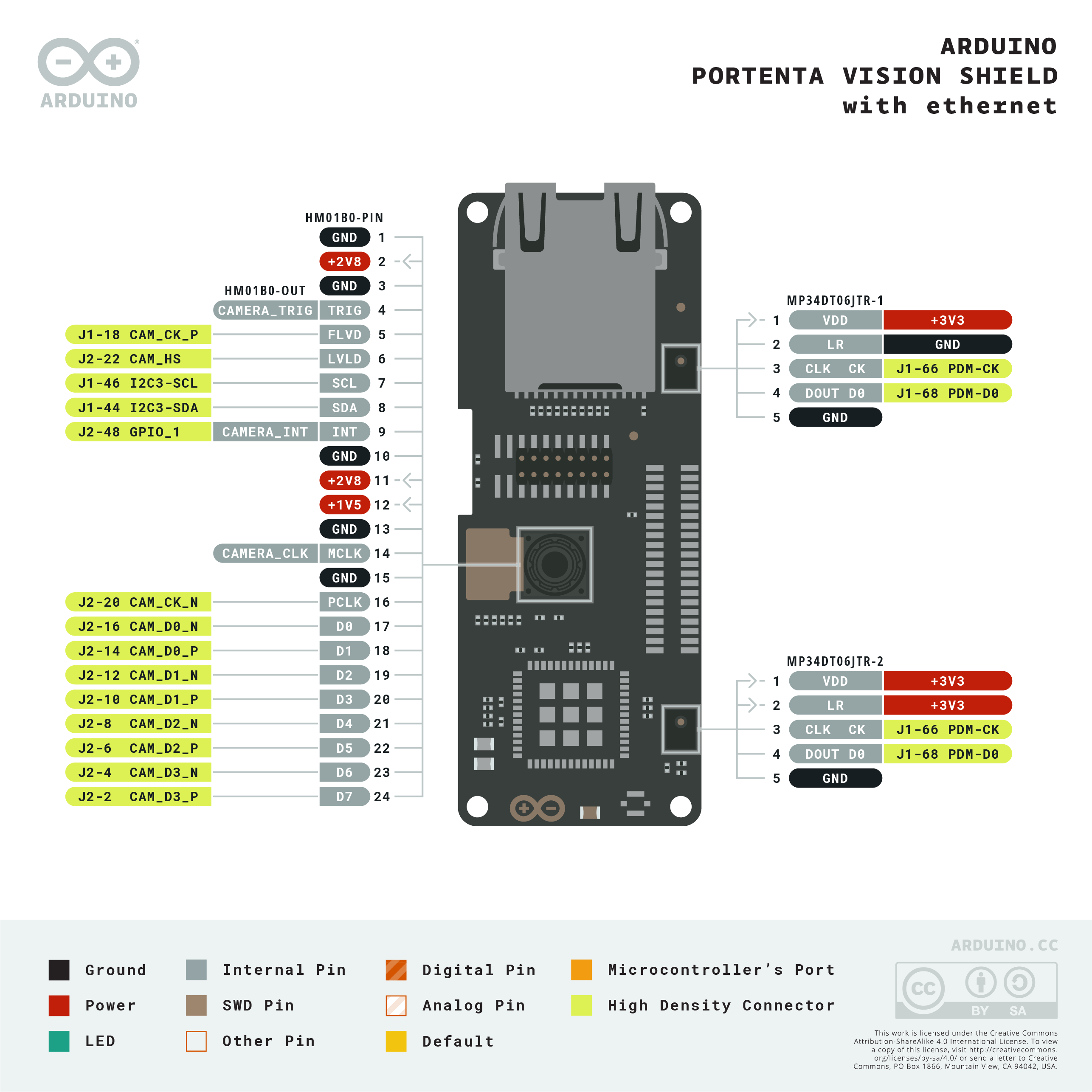
Download the full pinout diagram as PDF here.
Learn more
Get Inspired
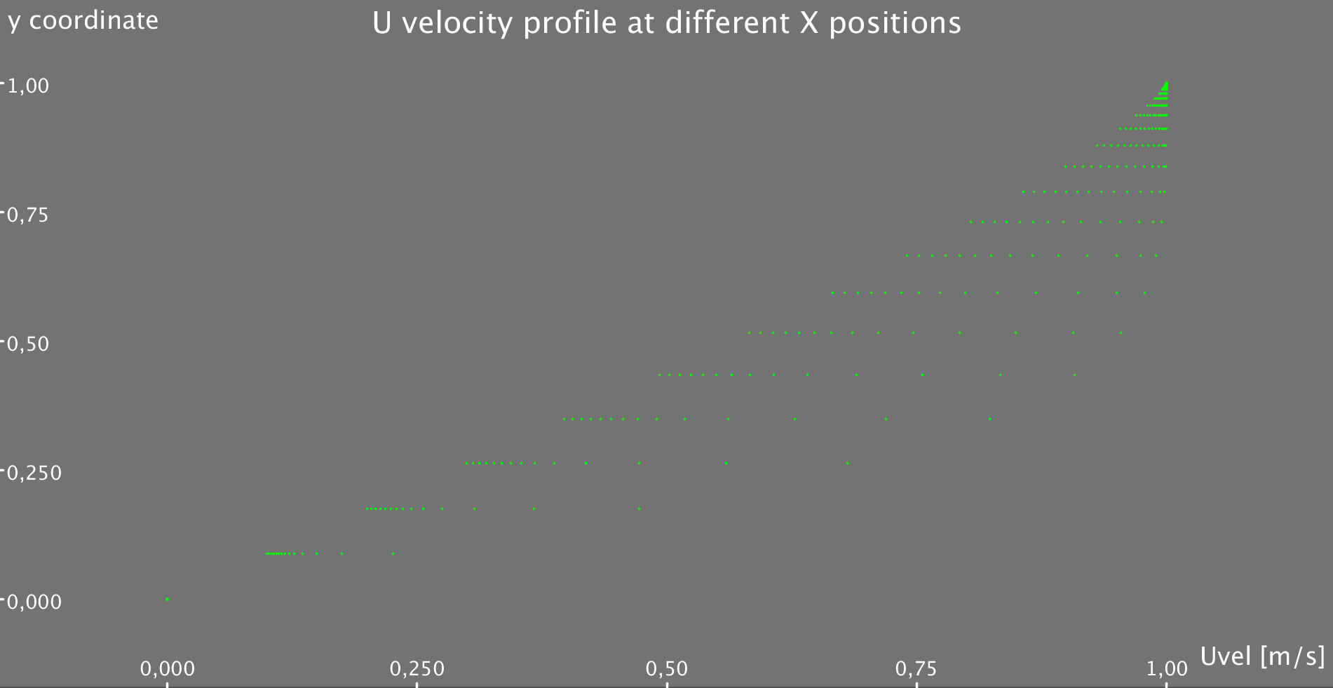
Simple Code that allows you to solve the 2D flow equation for a flat plate Boundary Layer!!
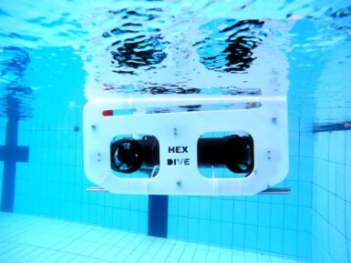
Who doesn’t want to explore underwater? To take a journey beneath the surface of a lake or even the ocean? But a remotely operated vehicle (ROV), which is the kind of robot you’d use for such an adventure, isn’t exactly the kind of thing you’ll find on the shelf at your local Walmart. You can, however, follow this guide from Ranuga Amarasinghe to build your own ROV for some aquatic fun. Amarasinghe is a 16-year-old Sri Lankan student and this is actually the second iteration of his ROV design. As such, he's dubbed it “ROV2” and it appears to be quite capable. All of its electronics sit safely within a 450mm length of sealed PVC tube. That mounts onto the aluminum extrusion frame structure that also hosts the six thrusters powered by drone-style brushless DC motors. ROV2’s brain is an Arduino Mega 2560 board and it drives the BLDC motors through six electronic speed controllers (ESCs). It receives control commands from the surface via an umbilical. The operator holds a Flysky transmitter that sends radio signals to a receiver floating on the water. An Arduino UNO Rev3 reads those and then communicates the motor commands to the Mega through the tethered serial connection. That limits the maximum length of the tether to about 40 meters, which subsequently limits the maximum operating depth. With the specified lithium battery pack, ROV2 can traverse the depths for 30-45 minutes. And when equipped with the 720p FPV camera, pilots can see and record all of the underwater action.


