Overview
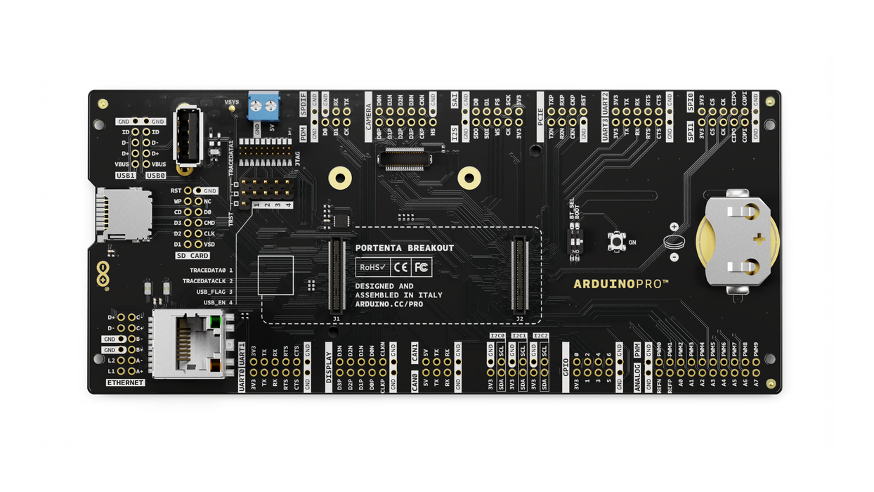
Portenta Breakout board is designed to help hardware engineers and makers to prototype and help test devices connections and capacity within the Portenta family boards (e.g. the Portenta H7).
It makes all high-density connectors’ signals individually accessible, making it quick and easy to connect and test external hardware components and devices as normally needed during development in the lab.
Target areas
Prototyping
Application examples
This product is designed to work alongside the Portenta family. Please check the Getting Started guide of your Portenta board.
Product Development: The Portenta Breakout board reduces development time for industrial grade solution automation based on the Portenta line.
Technical Education: The Portenta Breakout board can act as the first point of entry for technician education in industrial grade control and embedded systems.
Features
- Power ON Button
- Boot mode DIP switch
- Connectors
- USBA
- RJ45 up to 1Gb/s
- Micro SD card
- MIPI 20T JTAG with trace capability - Power
- CR2032 RTC Lithium Battery backup
- External power terminal block - I/O
- Break out all Portenta High Density connector signals
- Male/female HD connectors allow interposing breakout between Portenta and shield to debug signals - Compatibility
- Standard Portenta High Density connector pinout - Safety information
- Class A
Tech specs
| USB port | USBA |
| Ethernet | RJ45 up to 1Gb/s (Supported on Portenta X8 only) |
| Memory slot | Micro SD card |
| Debug | MIPI 20T JTAG with trace capability |
| Connectors | HD male/female |
| RTC power battery | CR2032 |
| Length | 164 mm |
| Width | 72 mm |
| Weight | 0,069 Kg |
Conformities
Resources for Safety and Products
Manufacturer Information
The production information includes the address and related details of the product manufacturer.
Arduino S.r.l.
Via Andrea Appiani, 25
Monza, MB, IT, 20900
https://www.arduino.cc/
Responsible Person in the EU
An EU-based economic operator who ensures the product's compliance with the required regulations.
Arduino S.r.l.
Via Andrea Appiani, 25
Monza, MB, IT, 20900
Phone: +39 0113157477
Email: support@arduino.cc
Documentation
Study how the Portenta Breakout Carrier works using following files:
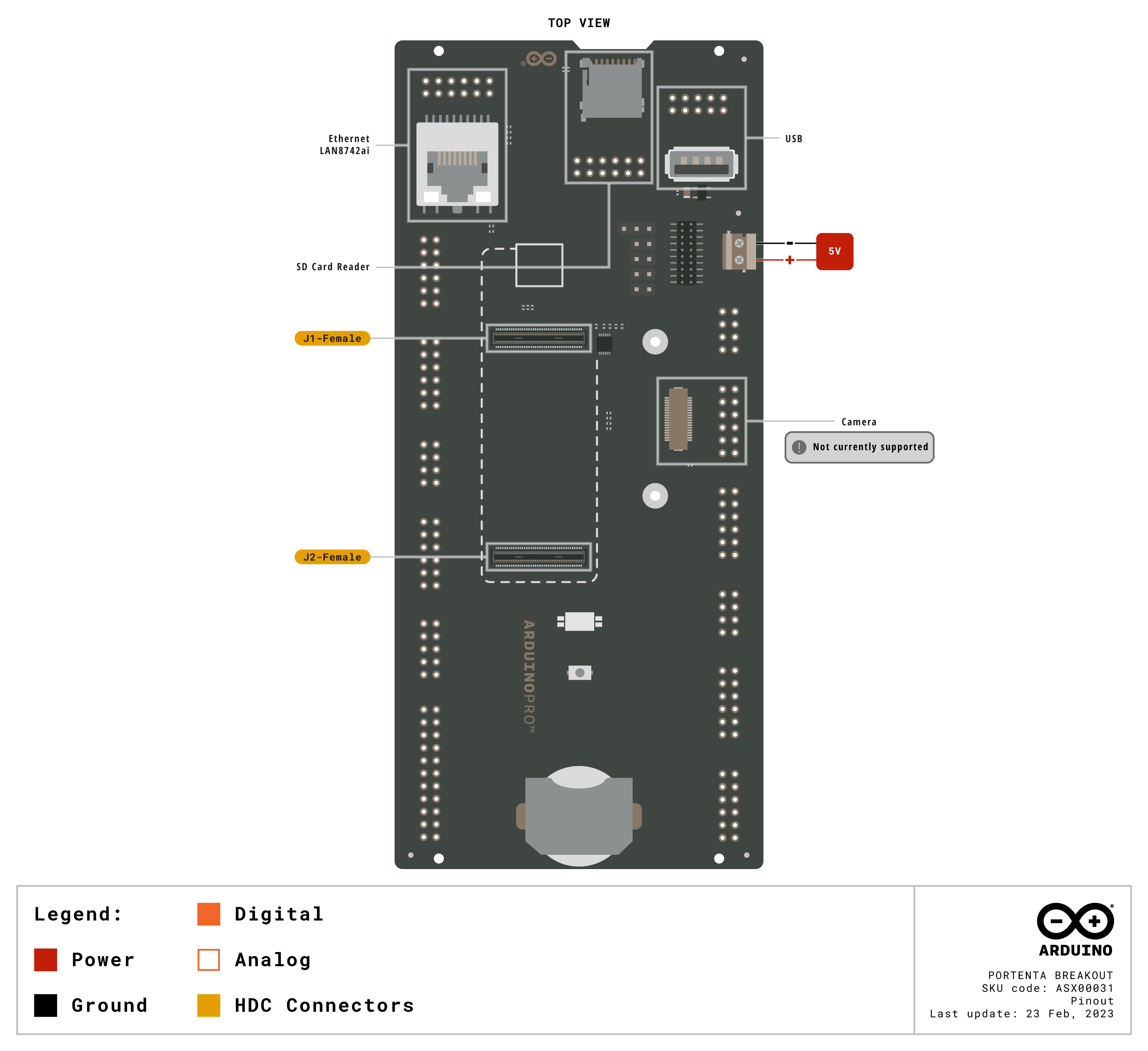
Pinout Diagram
Learn more about the portenta's pinout by reading the pinout documentation.

Download the full pinout diagram as PDF here.
Interactive Board Viewer
Learn more
Get Inspired
Print a claw on your 3D printer and use a myoelectric sensor to control it.

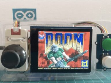
"But can it run Doom?" is more than just a joke in the tech world. It is also a decent litmus test for the computing power of hardware. That test isn't very relevant for modern computers, but it is still worth asking when discussing microcontrollers. Microcontrollers vary in dramatically in processing power and memory, with models to suit every application. But if you have an Arduino Nano ESP32 board, you can run Doom as Naveen Kumar has proven. The Nano ESP32 is a small IoT development board for the ESP32-S3 microcontroller, featuring Wi-Fi® and Bluetooth® connectivity. It also has a relatively high clock speed and quite a lot of memory: 240MHz and 512kB SRAM, respectively. That still isn't enough to meet the requirements of the original Doom release, which needed a lot more RAM. But Kumar demonstrates the use of an MCU-friendly port that runs well on this more limited hardware. Want to give it a try yourself? You'll need the Nano ESP32, an Adafruit 2.8" TFT LCD shield, an M5Stack joystick, a Seeed Studio Grove dual button module, a breadboard, and some jumper wires to create a simple handheld console. You'll have to compile and flash the Retro-Go firmware, which was designed specifically for running games like Doom on ESP32-based devices. You can then load the specialized WAD (Where's All the Data) files. Kumar reports an average frame rate at a 320×240 resolution, which is very playable.


