


Overview
The Arduino 4 Relays Shield is a solution for driving high power loads that cannot be controlled by Arduino's digital IOs, due to the current and voltage limits of the controller. The Shield features four relays, each relay provides 2 pole changeover contacts (NO and NC); in order to increase the current limit of each output the 2 changeover contacts have been put in parallel. Four LEDs indicate the on/off state of each relay.
Getting Started
You can find in the Getting Started section all the information you need to configure your board, use the Arduino Software (IDE), and start tinker with coding and electronics..
Need Help?
- On the Software on the Arduino Forum
- On Projects on the Arduino Forum
- On the Product itself through our Customer Support
Tech specs
Features
| Thinker Kit interface | 2x TWI, 2x OUT, 2x IN |
| Interfaces with Arduino Board | DIO |
| Relays | 4 (60W) |
General
| Operating Voltage | 5 V |
| Current needs | 140 mA (with all releays on, about 35 mA each) |
| PCB Size | 53 x 68.5 mm |
| Weight | 0.044 Kg |
| Product Code | A000110 |
Conformities
Resources for Safety and Products
Manufacturer Information
The production information includes the address and related details of the product manufacturer.
Arduino S.r.l.
Via Andrea Appiani, 25
Monza, MB, IT, 20900
https://www.arduino.cc/
Responsible Person in the EU
An EU-based economic operator who ensures the product's compliance with the required regulations.
Arduino S.r.l.
Via Andrea Appiani, 25
Monza, MB, IT, 20900
Phone: +39 0113157477
Email: support@arduino.cc
Documentation
OSH: Schematics
The Arduino 4 Relays Shield is open-source hardware! You can build your own board using the following files:
EAGLE FILES IN .ZIP SCHEMATICS IN .PDF
Description
|
Operating Voltage |
5V |
|
Coil current consumption |
140 mA (with all releays on, about 35 mA each) |
|
Single pole chargeover contact maximum current |
@ 30 V DC 2A |
|
Maximum load voltage |
48 V |
|
Maximum switching capacity |
60 W |
Power
The shield doesn't need external power: it will be provided by the base board, through the 5V and 3.3V pins of the Arduino board used as base.
Input and Output
The relays are controlled by the following Arduino board pins: Relay 1 = Arduino pin 4 Relay 2 = Arduino pin 7 Relay 3 = Arduino pin 8 Relay 4 = Arduino pin 12 The shield features several TinkerKit input/output and communication interfaces. Connecting TinkerKit modules can simplify the creation of a project or a prototype. The on-board connectors are :
- 2 TinkerKit Inputs: IN2 and IN3 (in white), these connectors are routed to the Arduino A2 and A3 analog input pins.
- 2 TinkerKit Outputs: OUT5 and OUT6 (in orange), these connectors are routed to the Arduino PWM outputs on pins 5 and 6.
- 2 TinkerKit TWI: these connectors (4-pin in white) are routed on the Arduino TWI interface. Both connect to the same TWI interface to allow you to create a chain of TWI devices.
Physical Characteristics
The maximum length and width of the 4 Relays Shield PCB are 2.7 and 2.1 inches respectively. Four screw holes allow the Shield to be attached to a surface or case. Note that the distance between digital pins 7 and 8 is 160 mil (0.16"), not an even multiple of the 100 mil spacing of the other pins.
Compatible Boards
The shield is compatible with all the Arduino boards, 5V and also 3.3V standards.
Learn more
Get Inspired
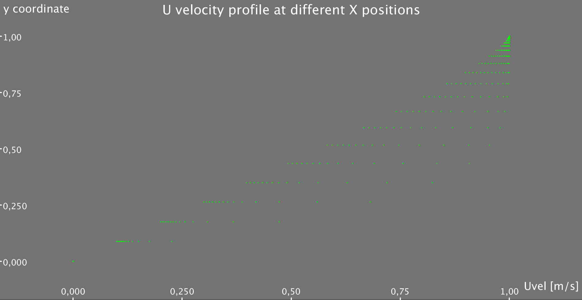
Simple Code that allows you to solve the 2D flow equation for a flat plate Boundary Layer!!
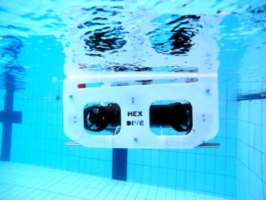
Who doesn’t want to explore underwater? To take a journey beneath the surface of a lake or even the ocean? But a remotely operated vehicle (ROV), which is the kind of robot you’d use for such an adventure, isn’t exactly the kind of thing you’ll find on the shelf at your local Walmart. You can, however, follow this guide from Ranuga Amarasinghe to build your own ROV for some aquatic fun. Amarasinghe is a 16-year-old Sri Lankan student and this is actually the second iteration of his ROV design. As such, he's dubbed it “ROV2” and it appears to be quite capable. All of its electronics sit safely within a 450mm length of sealed PVC tube. That mounts onto the aluminum extrusion frame structure that also hosts the six thrusters powered by drone-style brushless DC motors. ROV2’s brain is an Arduino Mega 2560 board and it drives the BLDC motors through six electronic speed controllers (ESCs). It receives control commands from the surface via an umbilical. The operator holds a Flysky transmitter that sends radio signals to a receiver floating on the water. An Arduino UNO Rev3 reads those and then communicates the motor commands to the Mega through the tethered serial connection. That limits the maximum length of the tether to about 40 meters, which subsequently limits the maximum operating depth. With the specified lithium battery pack, ROV2 can traverse the depths for 30-45 minutes. And when equipped with the 720p FPV camera, pilots can see and record all of the underwater action.


