


Arduino MKR Motor Carrier
Sold outWant to connect several motors and sensors to your mechatronic project? The Arduino MKR Motor Carrier is the perfect companion for Arduino MKR boards as it will allow you to rapidly prototyping and build your projects.
Overview
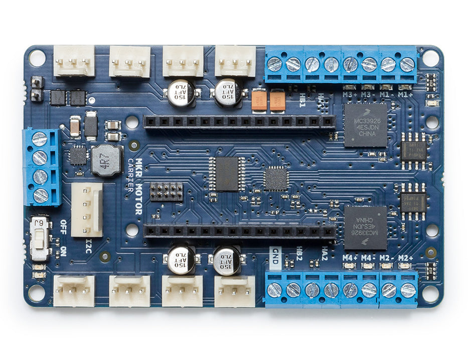
The MKR Motor Carrier is an MKR add-on board designed to control servo, DC, and stepper motors. The Carrier can also be used to connect other actuators and sensors via a series of 3-pin male headers.
The summary of features is shown below:
- Compatible with all the boards in the MKR family
- Four servo motor outputs
- Four DC motor outputs (two high performance + two standard performance)
- Sensing of current feedback for the high-performance motors
- Two inputs for encoder sensors
- Four inputs for analog sensors (3-pin compatible)
- Possibility to read the status of the batteries
- ON-OFF switch with Power ON LED
- LiPo battery connector (2S or 3S compatible) and power terminal block for alternative power source
- LEDs to visually indicate the direction of the rotation of the DC motors
- On-board processor for automated control of some of the outputs
- I2C connector as a 4-pin male header
Tech specs
|
Microcontroller |
ATSAMD11 ( Arm Cortex-M0+ processor) |
|
Max current (MC33926) |
5 Amps Peak, RMS current depending on the degree of heat sink provided |
|
Max current (DRV8871) |
3 Amps peak, current limited by current sense resistor. |
|
Rated voltage |
6.5 to 11.1V |
|
Reverse current protection |
Yes |
|
Over Temperature shutdown protection (for DC motor drivers) |
Yes |
|
Clock speed |
48 Mhz |
|
On board voltage regulator |
5V |
|
Interface |
Terminal block and 3 pin/4 pin header connector |
|
Compatibility |
MKR Family |
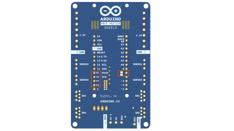
The MKR Motor Carrier features two MC33926 motor drivers for high-performance DC motor control with direct connection to the MKR1000, current feedback, and capacity for up to 5 Amps (peak). In addition, there are two DRV8871 drivers that are controlled from a SAMD11 microcontroller that communicates with the MKR1000 via I2C (SPI optional). The SAMD11 is also used to control the servos, read the encoders, and read the battery voltage. There is an interrupt line connecting the SAMD11 (on PA27) and the MKR board.
Note that for extended use or high-current motors, an extra heatsink (and eventually a fan) might be required for the drivers.
When plugging the MKR1000 and the Motor Carrier, some of the pins will stop being available for you to use in your code, as they will be needed to control some of the features of the Carrier. For example, the current feedback from the two MC33926 drivers is connected directly to some of the analog pins on the MKR1000. The following list explains which pins of the MKR1000 are used to control the Carrier:
- Analog pin A3 for current feedback from Motor3
- Analog pin A4 for current feedback from Motor4
- Digital pin D2 for IN2 signal for Motor3
- Digital pin D3 for IN1 signal for Motor3
- Digital pin D4 for IN2 signal for Motor4
- Digital pin D5 for IN1 signal for Motor4
- Digital pin D6 for Interrupt signal from the SAMD11 to the MKR1000
- Digital pin D11 for the SDA signal (I2C)
- Digital pin D12 for the SCL signal (I2C)
Also, some pins can optionally be connected via a soldering jumper or a 0 Ohm resistor. These pins are:
- Digital pin D1 for the SF signal from the MC33926 drivers (optional)
- Digital pin D7 for the SPI SS signal (optional)
- Digital pin D8 for the SPI MOSI signal (optional)
- Digital pin D9 for the SPI SCK signal (optional)
- Digital pin D10 for the SPI MISO signal (optional)
Libraries
MKR Motor carrier library
Conformities
Resources for Safety and Products
Manufacturer Information
The production information includes the address and related details of the product manufacturer.
Arduino S.r.l.
Via Andrea Appiani, 25
Monza, MB, IT, 20900
https://www.arduino.cc/
Responsible Person in the EU
An EU-based economic operator who ensures the product's compliance with the required regulations.
Arduino S.r.l.
Via Andrea Appiani, 25
Monza, MB, IT, 20900
Phone: +39 0113157477
Email: support@arduino.cc
Documentation
OSH: Schematics
The Arduino MKR Motor carrier is open-source hardware! You can build your own board using the following files:
EAGLE FILES IN .ZIP SCHEMATICS IN .PDFLearn more
Get Inspired
If you’re interested in embedded machine learning (TinyML) on the Arduino Nano 33 BLE Sense, you’ll have found a ton of on-board sensors — digital microphone, accelerometer, gyro, magnetometer, light, proximity, temperature, humidity and color — but realized that for vision you need to attach an external camera. In this article, we will show you how to get image data from a low-cost VGA camera module. We’ll be using the Arduino_OVD767x library to make the software side of things simpler. Hardware setup To get started, you will need: Arduino Nano 33 BLE Sense with headersOV7670 CMOS VGA Camera Module 16x female to female jumper wiresA microUSB cable to connect to your Arduino You can of course get a board without headers and solder instead, if that's your preference. The one downside to this setup is that (in module form) there are a lot of jumpers to connect. It’s not hard but you need to take care to connect the right cables at either end. You can use tape to secure the wires once things are done, lest one comes loose. You need to connect the wires as follows: Software setup First, install the Arduino IDE or register for Arduino Create tools. Once you install and open your environment, the camera library is available in the library manager. Install the Arduino IDE or register for Arduino CreateTools > Manage Libraries and search for the OV767 libraryPress the Install button Now, we will use the example sketch to test the cables are connected correctly: Examples > Arduino_OV767X > CameraCaptureRawBytesUncomment (remove the //) from line 48 to display a test pattern Compile and upload to your board Your Arduino is now outputting raw image binary over serial. To view this as an image we’ve included a special application to view the image output from the camera using Processing. Processing is a simple programming environment that was created by graduate students at MIT Media Lab to make


