

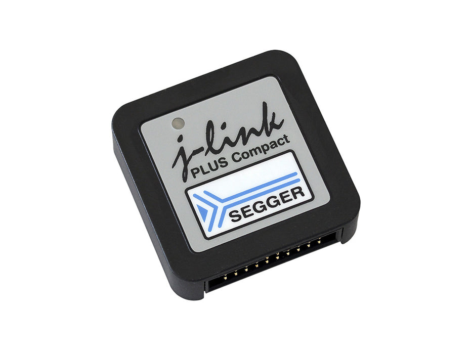
J-Link PLUS Compact
Sold outUSB powered JTAG debug probe supporting a large number of CPU cores.
Based on a 32-bit RISC CPU, it can communicate at high speed with the supported target CPUs.
SEGGER J-Link PLUS Compact is used around the world in tens of thousand places for development and production (flash programming) purposes.
Overview
Get the SEGGER J-Link PLUS Compact debug probe: a compact version of the J-Link PLUS. Mounts securely & unobtrusively into development and end user equipment.
Based on 32-bit RISC CPU, it communicates at high speed with supported target CPUs.
Thanks to a small size with two mounting holes, it can be placed into existing equipment housings.
Space can also be reserved for direct-to-PCB mounting.
All major IDEs (Eclipse & GDB-based IDEs) support J-Link debug probes, as does SEGGER Embedded Studio. 500,000 J-Links have been shipped so far, making this probably the most popular debug probe on the market for Arm cores and the de-facto standard.
Further Advantages
The SEGGER J-Link PLUS Compact has a built-in VCOM functionality and integrated licenses for unlimited breakpoints in flash memory, RDI/RDDI and J-Flash. It supports direct download into RAM and flash memory. It has a broad range of supported microcontrollers and CPUs.
Box Contents
- SEGGER J-Link PLUS Compact debug probe
- Micro USB cable
- 1" 20-pin ribbon cable (18 cm)
- Includes free software updates and one year of email support.
SEGGER J-Link debuggers are the most popular choice for optimizing the debugging and flash programming experience.
Documentation
Debugging with the Arduino IDE 2.0
Learn how to set up a Zero board, J-Link and Atmel-ICE debuggers with the Arduino IDE 2.0, and how to debug a program.
Using the Segger J-Link debugger with the MKR boards
Learn how to set up a MKR board with the Segger J-link debugger.
Get Inspired
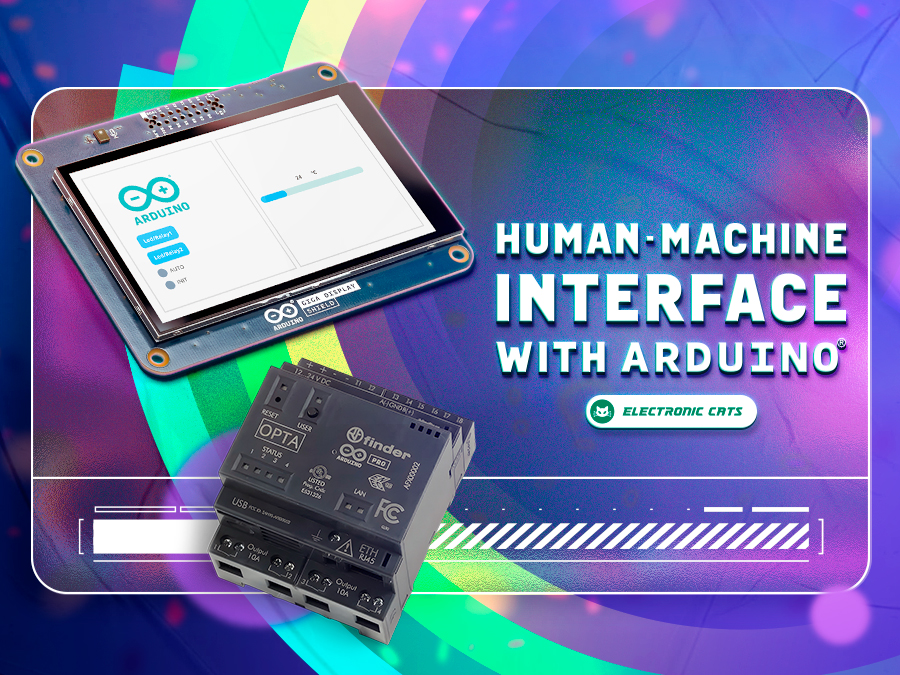
Learn how to build a complete HMI with Arduino that will allow you to interact with your projects in an intuitive and visual way.

OPC Unified Architecture – OPC UA in short – is a cross-platform, open-source machine-to-machine communication protocol for industrial automation. It was developed by the Open Platform Communications (OPC) Foundation and is defined in detail in the IEC 62541 standard. With the release of the Arduino_OPC_UA library we enable users to convert any product from our Arduino Opta range into an OPC UA-enabled device. Step-by-step guide to setting up OPC UA on Arduino Opta It’s as simple as uploading a single sketch onto your Opta and connecting it to an Ethernet network. Once uploaded, the OPC UA firmware exposes the Arduino Opta’s analog and digital inputs, the user button and LED (only Arduino Opta WiFi), as well as its relay outputs as properties that can be read from or written to using OPC UA. OPC UA communication is performed using OPC UA binary encoding via TCP sockets. Arduino_OPC_UA is a port of the Fraunhofer open62541 library implementing IEC 62541 in highly portable C99 for both Windows and Linux targets. One serious challenge during the porting of open62541 was to decide on sensible tradeoffs concerning RAM consumption, as using OPC UAs full namespace zero (NS0) requires up to 8 MB of RAM while the STM32H747 powering the Arduino Opta has a total of 1 MB of SRAM to offer – some of which already allocated by the the Arduino framework for the Arduino Opta. Expand functionality with Arduino Opta Modules and OPC UA integration Additionally, Arduino_OPC_UA supports the automatic discovery, configuration and exposure as OPC UA objects of the recently released Arduino Opta expansion modules. Currently three different expansion modules exist: Arduino Opta Analog Expansion (A0602), Arduino Opta Digital Expansion with electro-mechanical relay outputs (D1608E), and with solid-state relay outputs (DS1608S). During system start-up, the Arduino Opta’s expansion bus is queried for connected expansion modules and automatically configures them and


