


Overview
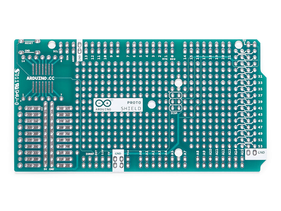
The Arduino Prototyping Shield makes it easy for you to design custom circuits. You can solder parts to the prototyping area to create your project,or use it with a small solderless breadboard (not included) to quickly test circuit ideas without having to solder. It's got extra connections for all of the Arduino MEGA I/O pins, and it's got space to mount through-hole and surface mount integrated circuits. It's a convenient way to make your custom Arduino circuit into a single module.
Getting Started
You can find in the Getting Started section all the information you need to configure your board, use the Arduino Software (IDE), and start tinker with coding and electronics..
Need Help?
- On the Software on the Arduino Forum
- On Projects on the Arduino Forum
- On the Product itself through our Customer Support
Tech specs
General
| PCB Size | 101.5 x 53.3 mm |
| Weight | 0.013 Kg |
Conformities
Resources for Safety and Products
Manufacturer Information
The production information includes the address and related details of the product manufacturer.
Arduino S.r.l.
Via Andrea Appiani, 25
Monza, MB, IT, 20900
https://www.arduino.cc/
Responsible Person in the EU
An EU-based economic operator who ensures the product's compliance with the required regulations.
Arduino S.r.l.
Via Andrea Appiani, 25
Monza, MB, IT, 20900
Phone: +39 0113157477
Email: support@arduino.cc
Documentation
OSH: Schematics
The Arduino Mega Proto Shield is open-source hardware! You can build your own board using the following files:
EAGLE FILES IN .ZIP SCHEMATICS IN .PDF
Description
Board features as follows:
- 1.0 Arduino pinout
- 1 Reset button
- 1 ICSP connector
- 14 pins SMD footprint (50 mils pitch)
- 32 double row through Hole pads, standard Arduino breakout layout
- Proto aerea with multiple THT pads, 100 mils pitch
Power
The Proto Shield bring the power from the Arduino standard 5V and GND pins to the two power bus rows placed between the Through Hole package footprint, which can be used for powering the DIP sockets, or for power and ground rows.
Physical Characteristics
The maximum length and width of the Proto Shield PCB are 2.7 and 2.1 inches respectively. Three screw holes allow the shield to be attached to a surface or case. Note that the distance between digital pins 7 and 8 is 160 mil (0.16"), not an even multiple of the 100 mil spacing of the other pins.
SPI Connection
On the ICSP connector only 5V, GND and RST are wired to the respective pins on the header. MOSI and MISO are present only on the connector pads. For more information about the SPI communication see the SPI library.
Get Inspired

This code sets up an Arduino device to connect to WiFi and communicate with the OpenAI API. It uses the Adafruit_SSD1306 library to control a small OLED display, displaying messages and responses from the API. The device sends a prompt to the API asking "What is Arduino?" and waits for a response, which it then displays on the OLED screen. This is done using a secure SSL connection, and the API key is stored as a variable in the code. Overall, this code demonstrates how an Arduino device can be used to interact with web services and display data on a small screen.
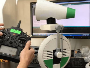
While it’s yet to make its premiere, Matt Denton has already built the D-O droid from Star Wars: The Rise of Skywalker using a MKR WiFi 1010 for control, along with a MKR IMU Shield and a MKR Motor Carrier. The droid scoots around on what appears to be one large wheel, which conceals the Arduino boards as well as other electronics, batteries, and mechanical components. Denton’s wheel design is a bit more complicated mechanically than it first appears, as its split into a center section, with thin drive wheels on the side that enable differential steering. On top, a cone-shaped head provides sounds and movement, giving the little RC D-O a ton of personality. The droid isn’t quite finished as of the video below, but given how well it works there, the end product should be amazing!


