


Overview
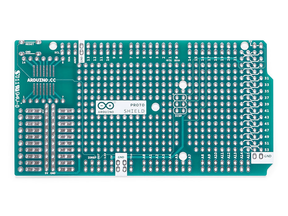
The Arduino Prototyping Shield makes it easy for you to design custom circuits. You can solder parts to the prototyping area to create your project,or use it with a small solderless breadboard (not included) to quickly test circuit ideas without having to solder. It's got extra connections for all of the Arduino MEGA I/O pins, and it's got space to mount through-hole and surface mount integrated circuits. It's a convenient way to make your custom Arduino circuit into a single module.
Getting Started
You can find in the Getting Started section all the information you need to configure your board, use the Arduino Software (IDE), and start tinker with coding and electronics..
Need Help?
- On the Software on the Arduino Forum
- On Projects on the Arduino Forum
- On the Product itself through our Customer Support
Tech specs
General
| PCB Size | 101.5 x 53.3 mm |
| Weight | 0.013 Kg |
Conformities
Resources for Safety and Products
Manufacturer Information
The production information includes the address and related details of the product manufacturer.
Arduino S.r.l.
Via Andrea Appiani, 25
Monza, MB, IT, 20900
https://www.arduino.cc/
Responsible Person in the EU
An EU-based economic operator who ensures the product's compliance with the required regulations.
Arduino S.r.l.
Via Andrea Appiani, 25
Monza, MB, IT, 20900
Phone: +39 0113157477
Email: support@arduino.cc
Documentation
OSH: Schematics
The Arduino Mega Proto Shield is open-source hardware! You can build your own board using the following files:
EAGLE FILES IN .ZIP SCHEMATICS IN .PDF
Description
Board features as follows:
- 1.0 Arduino pinout
- 1 Reset button
- 1 ICSP connector
- 14 pins SMD footprint (50 mils pitch)
- 32 double row through Hole pads, standard Arduino breakout layout
- Proto aerea with multiple THT pads, 100 mils pitch
Power
The Proto Shield bring the power from the Arduino standard 5V and GND pins to the two power bus rows placed between the Through Hole package footprint, which can be used for powering the DIP sockets, or for power and ground rows.
Physical Characteristics
The maximum length and width of the Proto Shield PCB are 2.7 and 2.1 inches respectively. Three screw holes allow the shield to be attached to a surface or case. Note that the distance between digital pins 7 and 8 is 160 mil (0.16"), not an even multiple of the 100 mil spacing of the other pins.
SPI Connection
On the ICSP connector only 5V, GND and RST are wired to the respective pins on the header. MOSI and MISO are present only on the connector pads. For more information about the SPI communication see the SPI library.
Get Inspired
Control everything with a SINGLE phone call.
… between the Rev2 and the previous version of the MKR IoT Carrier. Here are the main ones. Some sensors have changed: The humidity sensor (HTS221) and barometric pressure sensor (LP22HB) has been replaced with the BME688 sensor.The IMU (LSM6DS3) was replaced with LSM6DSOX. Following customer feedback some other components have been repositioned: Addition of a handy reset button90° rotation of the relay connectorsRepositioning of the light sensor (APDS-9960)Change of pins assigned to control the relays to pins 1 and 2Change grove connector assignment from pin A5 to A6 Do I have to change my sketch if I have been using the first revision of the MKR IoT Carrier? No — the MKR IoT Carrier library works with both revisions of the carrier. Just make sure to use the latest version of the library to ensure everything goes smoothly. Have more fun with the IoT The new MKR IoT Carrier Rev2 is the perfect tool to get started having fun with your own IoT projects, or to take your IoT tinkering to the next level. You don’t need a ton of experience, a bucket of expensive components, or endless hours of free time to build your own satisfying, useful IoT gadgets at home. Discover the MKR IoT Carrier Rev2


