Overview
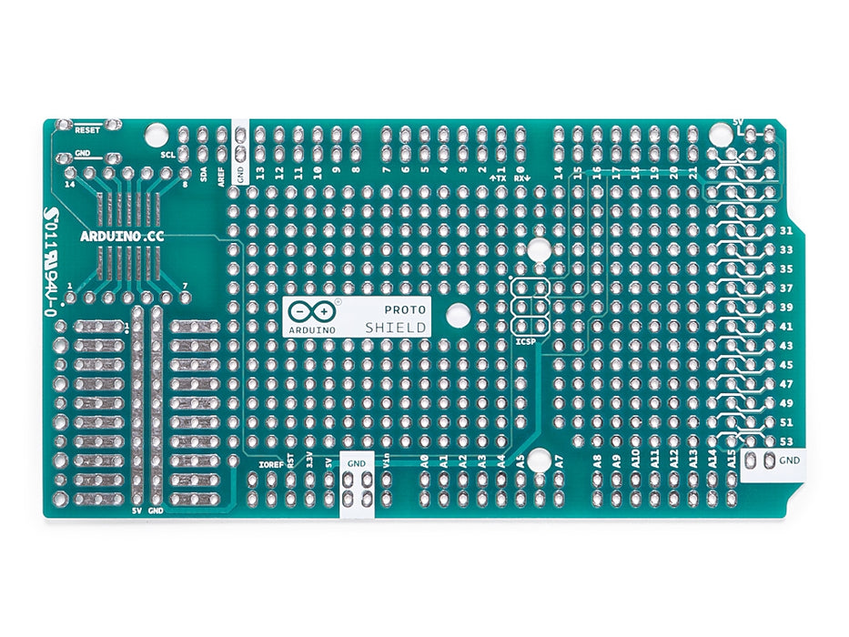
The Arduino Prototyping Shield makes it easy for you to design custom circuits. You can solder parts to the prototyping area to create your project,or use it with a small solderless breadboard (not included) to quickly test circuit ideas without having to solder. It's got extra connections for all of the Arduino MEGA I/O pins, and it's got space to mount through-hole and surface mount integrated circuits. It's a convenient way to make your custom Arduino circuit into a single module.
Getting Started
You can find in the Getting Started section all the information you need to configure your board, use the Arduino Software (IDE), and start tinker with coding and electronics..
Need Help?
- On the Software on the Arduino Forum
- On Projects on the Arduino Forum
- On the Product itself through our Customer Support
Tech specs
General
| PCB Size | 101.5 x 53.3 mm |
| Weight | 0.013 Kg |
Conformities
Resources for Safety and Products
Manufacturer Information
The production information includes the address and related details of the product manufacturer.
Arduino S.r.l.
Via Andrea Appiani, 25
Monza, MB, IT, 20900
https://www.arduino.cc/
Responsible Person in the EU
An EU-based economic operator who ensures the product's compliance with the required regulations.
Arduino S.r.l.
Via Andrea Appiani, 25
Monza, MB, IT, 20900
Phone: +39 0113157477
Email: support@arduino.cc
Documentation
OSH: Schematics
The Arduino Mega Proto Shield is open-source hardware! You can build your own board using the following files:
EAGLE FILES IN .ZIP SCHEMATICS IN .PDF
Description
Board features as follows:
- 1.0 Arduino pinout
- 1 Reset button
- 1 ICSP connector
- 14 pins SMD footprint (50 mils pitch)
- 32 double row through Hole pads, standard Arduino breakout layout
- Proto aerea with multiple THT pads, 100 mils pitch
Power
The Proto Shield bring the power from the Arduino standard 5V and GND pins to the two power bus rows placed between the Through Hole package footprint, which can be used for powering the DIP sockets, or for power and ground rows.
Physical Characteristics
The maximum length and width of the Proto Shield PCB are 2.7 and 2.1 inches respectively. Three screw holes allow the shield to be attached to a surface or case. Note that the distance between digital pins 7 and 8 is 160 mil (0.16"), not an even multiple of the 100 mil spacing of the other pins.
SPI Connection
On the ICSP connector only 5V, GND and RST are wired to the respective pins on the header. MOSI and MISO are present only on the connector pads. For more information about the SPI communication see the SPI library.
Get Inspired

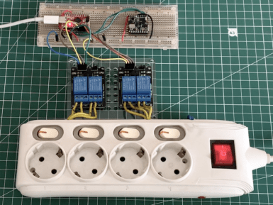
As Jallson Suryo discusses in his project, adding voice controls to our appliances typically involves an internet connection and a smart assistant device such as Amazon Alexa or Google Assistant. This means extra latency, security concerns, and increased expenses due to the additional hardware and bandwidth requirements. This is why he created a prototype based on an Arduino Nicla Voice that can provide power for up to four outlets using just a voice command. Suryo gathered a dataset by repeating the words “one," “two," “three," “four," “on," and “off” into his phone and then uploaded the recordings to an Edge Impulse project. From here, he split the files into individual words before rebalancing his dataset to ensure each label was equally represented. The classifier model was trained for keyword spotting and used Syntiant NDP120-optimal settings for voice to yield an accuracy of around 80%. Apart from the Nicla Voice, Suryo incorporated a Pro Micro board to handle switching the bank of relays on or off. When the Nicla Voice detects the relay number, such as “one” or “three," it then waits until the follow-up “on” or “off” keyword is detected. With both the number and state now known, it sends an I2C transmission to the accompanying Pro Micro which decodes the command and switches the correct relay. To see more about this voice-controlled power strip, be sure to check out Suryo’s Edge Impulse tutorial.


